Supercharge Your Innovation With Domain-Expert AI Agents!

Heterogeneous multi-heat-source co-storage device

A multi-heat source, heterogeneous technology, applied to centralized heating, can solve problems such as large temperature fluctuations, unstable heat load, and low heat storage density

Pending Publication Date: 2021-06-15
SHANDONG UNIV
View PDF6 Cites 0 Cited by
  • Summary
  • Abstract
  • Description
  • Claims
  • Application Information

AI Technical Summary

Problems solved by technology

Sensible heat and thermochemical heat storage technology have the disadvantages of low heat storage density, large temperature fluctuations in the heat storage and release process, and unstable heat load.
Moreover, the inventors found that in the vast rural areas, it is generally in the form of non-centralized heating. At the present stage, it is mainly coal-fired, with other forms of heat sources, and the utilization rate of heat energy from different heat sources is low. Satisfy the stable heat utilization temperature range, let alone achieve the goal of carbon emission reduction

Method used


Image

  • Heterogeneous multi-heat-source co-storage device
  • Heterogeneous multi-heat-source co-storage device
  • Heterogeneous multi-heat-source co-storage device

Examples


Embodiment 1

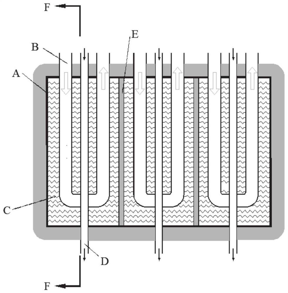
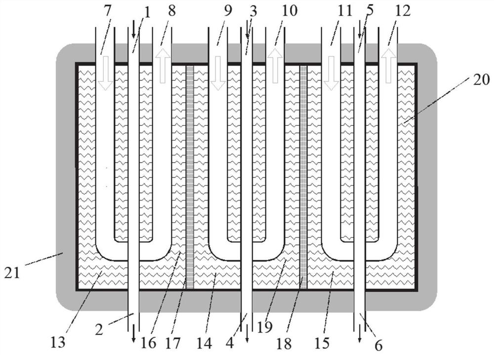
[0066] A heterogeneous heterogeneous multi-heat source co-storage device includes a shell A, a heat release tube B, several phase-change heat storage units C, a heat storage tube D, and two heat-insulating partitions E.

[0067] There are three phase change regions, which are the primary thermal storage unit 13 , the secondary thermal storage unit 14 , and the tertiary thermal storage unit 15 .

[0068] The interface between the heat release tube B and each heat storage unit is the inlet 7 of the first-level heat release tube; the outlet 8 of the first-level heat release tube; the inlet 9 of the second-level heat release tube; the outlet 10 of the second-level heat release tube; Heat pipe outlet 12.

[0069] The interface between the heat storage tube D and each heat storage unit is the heat storage tube inlet 1 of the first-level phase change heat storage unit; the heat storage tube outlet 2 of the first-level phase change heat storage unit; the heat storage tube inlet 3 of t...

Embodiment 2

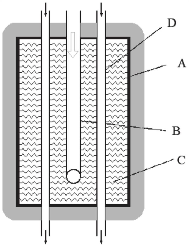
[0079] A multi-heat source phase change heat storage and heat release integrated device with a fin heat exchange structure inside the heat storage unit of this embodiment includes a shell A, a heat release pipe part B, a first-stage phase change heat storage unit C,

[0080] Heat storage tube part D and three compartments E in the first-stage phase change heat storage unit;

[0081] Wherein, heat release pipe part B includes heat release pipe inlet, heat release pipe outlet

[0082] The phase change thermal storage unit C includes a primary thermal storage unit 13 , a secondary thermal storage unit 14 and a tertiary thermal storage unit 15 .

[0083] The heat storage pipe part D includes the heat storage pipe inlet 1 of the first-stage phase change heat storage unit; the heat storage pipe outlet 2 of the first-stage phase change heat storage unit; the heat storage pipe inlet 3 of the second-stage phase change heat storage unit; Exit 4; Inlet 5 of the heat storage tube of the ...


PUM

PropertyMeasurementUnit
Thicknessaaaaaaaaaa
Phase transition temperatureaaaaaaaaaa

Abstract

The invention relates to a heterogeneous multi-heat-source co-storage device. The heterogeneous multi-heat-source co-storage device comprises a shell, wherein multiple phase change areas are arranged in the shell, and each phase change area is filled with a phase change material, and each phase change area forms a respective heat storage unit; heat storage pipes, wherein one heat storage pipe is arranged in each phase change area of each heat storage unit; and heat release pipes, wherein the heat release pipes sequentially penetrate through the phase change areas of the heat storage units according to a sequence from low-temperature areas to high-temperature areas, or each phase change area is provided with one heat release pipe, and the parts, located on the outer side of the shell, of the heat release pipes of the adjacent phase change areas are connected with each other or the heat release pipes of the adjacent phase change areas exist independently. The heat storage pipes transfer heat of heat sources to the phase change materials, the heat storage pipes in different phase change areas can be connected with different heat sources, multi-heat-source co-storage is achieved, the heat release pipes penetrate through the multiple phase change areas and can conduct heat exchange on the phase change materials in different areas at the same time, heat storage is conducted through different heat sources, and the supply stability of heat can be met; and the adaptation to different heat source environments is facilitated.

Description

technical field [0001] The invention belongs to the technical field of storage and utilization of different heat sources at different temperatures, and in particular relates to a heterogeneous heterogeneous multi-heat source co-storage device. Background technique [0002] The information disclosed in this background section is only intended to increase the understanding of the general background of the present invention, and is not necessarily taken as an acknowledgment or any form of suggestion that the information constitutes the prior art already known to those skilled in the art. [0003] The innovation of energy forms and the development of energy technology are of great significance to national economic development and social progress. In order to significantly reduce the pollutants produced in the heating process and reduce the damage to the environment, people began to explore new energy consumption methods. Now the development and utilization of single energy is gr...

Claims


Application Information

Patent Timeline
IPC IPC(8): F24D11/00F28D20/02
CPCF24D11/00F28D20/021Y02E60/14
Inventor 孙奉仲李英
Owner SHANDONG UNIV
Features
  • R&D
  • Intellectual Property
  • Life Sciences
  • Materials
  • Tech Scout
  • Unparalleled Data Quality
  • Higher Quality Content
  • 60% Fewer Hallucinations
Learn More