Environment-friendly water quality monitoring equipment

A technology for water quality monitoring and equipment, applied in the direction of testing water, unmanned surface ships, material inspection products, etc., can solve the problems of troublesome use of equipment, time-consuming, easy to obtain erroneous data, etc., to achieve convenient operation, energy saving, measurement full effect of results

Pending Publication Date: 2021-06-15
徐启楠
View PDF10 Cites 1 Cited by
  • Summary
  • Abstract
  • Description
  • Claims
  • Application Information

AI Technical Summary

Problems solved by technology

[0003] However, the existing water quality monitoring equipment is generally fixed at a certain position. When the water quality needs to be tested, it is turned on and then measured. The adjustment of the position and height cannot be realized, and the water at any position and liquid level cannot be adjusted. There are many restrictions on monitoring, and the monitoring data of various locations in the water area cannot be obtained, so there is a problem of incomplete measurement results; some water quality monitoring equipment put the equipment into the water when the water quality needs to be monitored, and monitor in real time. After taking out the device, this kind of device is more troublesome to use and needs to be taken and used at any time, and needs to be moved back after use, and the monitoring area is generally in a relatively remote area with few people, so it cannot be conveniently charged. During use, if the device Insufficient power, you have to bring the device back to full charge and then go to the water area to be tested for monitoring. The whole process takes a long time and is troublesome; some water quality monitoring equipment has more sediment and impurities attached to the outer surface of the monitoring head after long-term monitoring , so that the monitoring head cannot be kept clean, there will be errors in water quality monitoring, and it is easy to get wrong data, resulting in misjudgment

Method used


Image

  • Environment-friendly water quality monitoring equipment
  • Environment-friendly water quality monitoring equipment
  • Environment-friendly water quality monitoring equipment

Examples


Embodiment

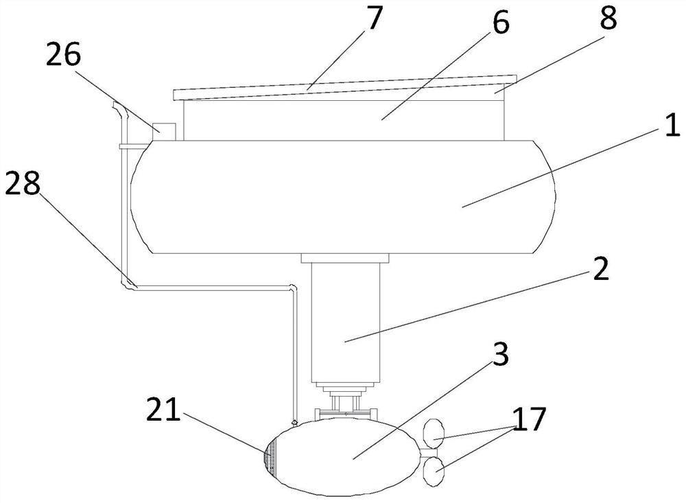
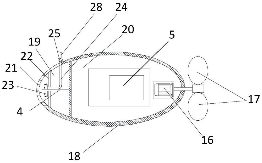
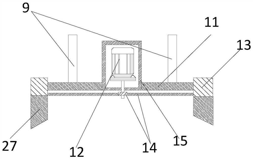
[0035] Please refer to Figure 1-5 , figure 1 It is the front view of the environmental protection water quality monitoring equipment of the embodiment of the present invention; figure 2 It is a schematic cross-sectional structure diagram of the housing of the environmental protection water quality monitoring equipment according to the embodiment of the present invention; image 3 It is a structural schematic diagram of the rotating device of the environmental protection water quality monitoring equipment according to the embodiment of the present invention; Figure 4 It is a top view of the rotating device of the environmental protection water quality monitoring equipment of the embodiment of the present invention; Figure 5 It is a structural schematic diagram of the solar charging device of the environmental protection water quality monitoring equipment of the embodiment of the present invention; Image 6 It is a structural block diagram of the environmental protection ...


PUM


Abstract

The invention provides environment-friendly water quality monitoring equipment, which relates to the technical field of water quality monitoring. The environment-friendly water quality monitoring equipment comprises a solar charging device used for supplying power, a suspension block installed at the bottom of the solar charging device, a lifting rod installed at the bottom of the suspension block, a rotating device connected with the bottom of the lifting rod, a containing shell installed at the bottom of the rotating device, a propelling device and a water quality monitor installed in the containing shell, a controller electrically connected with the solar charging device, the lifting rod, the propelling device and the water quality monitor and located in the containing shell, and a flushing device arranged on the containing shell. The solar charging device is installed above the suspension block, so that the equipment can convert solar energy into electric energy through illumination, power supply to the equipment is achieved, operation is convenient, self-charging is not needed, and energy is saved.

Description

technical field [0001] The invention relates to the technical field of water quality monitoring, in particular to an environment-friendly water quality monitoring device. Background technique [0002] With the country's increasing emphasis on environmental protection, the importance of water quality monitoring is constantly being emphasized. With the development of industry, the continuous increase of our population, and the rapid increase and expansion of the number and scale of cities, the problem of sewage is becoming more and more serious, and the pollution of water areas is becoming more and more serious. Each area is monitored. Water quality monitoring is the process of monitoring and measuring the types of pollutants in the water body, the concentration and change trend of various pollutants, and evaluating the water quality status. [0003] However, the existing water quality monitoring equipment is generally fixed at a certain position. When the water quality need...

Claims


Application Information

Patent Timeline
IPC IPC(8): G01N33/18B63H1/14B63B35/00H02J7/35B08B5/02
CPCG01N33/18B63B35/00B63H1/14H02J7/35B08B5/02B63B2035/008Y02A20/20
Inventor 徐启楠
Owner 徐启楠
Why Eureka
Try Eureka