Wind power converter control method, power equipment control device and converter

A technology of wind power converter and control method, which is applied in wind power generation, output power conversion device, AC power input conversion to AC power output, etc., which can solve the problem of polluting the power grid, increase the volume of the converter, and increase the number of converters Cost and other issues

Active Publication Date: 2021-06-15
SHENZHEN HOPEWIND ELECTRIC CO LTD
View PDF4 Cites 2 Cited by
  • Summary
  • Abstract
  • Description
  • Claims
  • Application Information

AI Technical Summary

Problems solved by technology

[0003] At present, the three-level topology generally adopts space vector modulation or carrier layer stacking. It will generate a large current three times its operating frequency at the midpoint of the busbar, and the positive and negative busbar voltage ripples will also be relatively large, especially when the motor operating frequency is low and the power factor is low, the busbar voltage ripple will be large. This will reduce the life

Method used


Image

  • Wind power converter control method, power equipment control device and converter
  • Wind power converter control method, power equipment control device and converter
  • Wind power converter control method, power equipment control device and converter

Examples


Embodiment 1

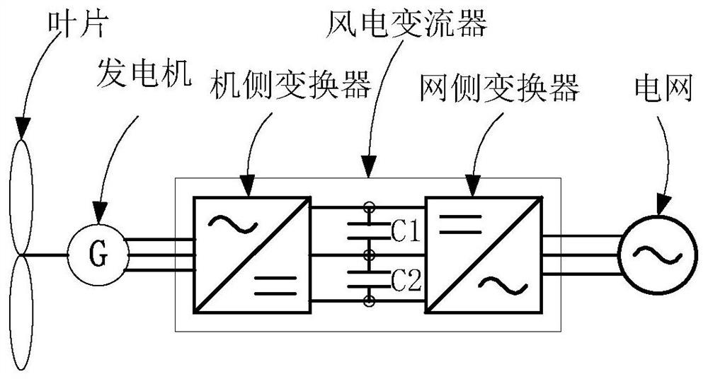
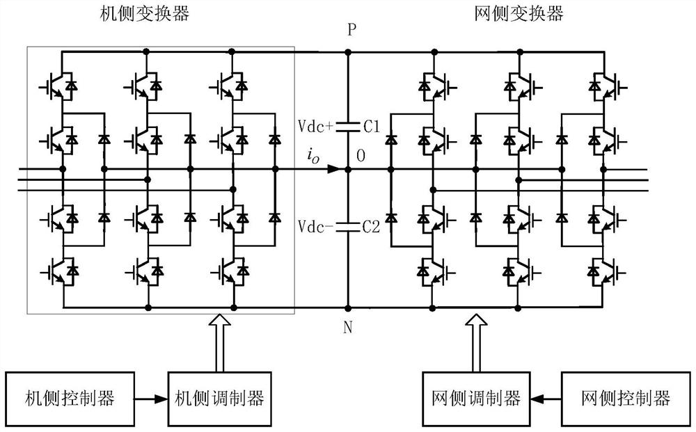
[0022] see figure 1 and figure 2 , figure 1 It is the overall structural diagram of the wind power converter of the present invention; figure 2 It is a structural diagram of a wind power converter and its controller and modulator of the present invention; this embodiment discloses a control method for a wind power converter, and provides a wind power converter, the wind power converter includes a grid-side converter, A generator-side converter, a grid-side controller, and a generator-side controller, the grid-side controller controls the grid-side converter to transmit waves with three-level unipolarity, and the generator-side controller controls the generator-side converter The device adopts three-level bipolar wave transmission.

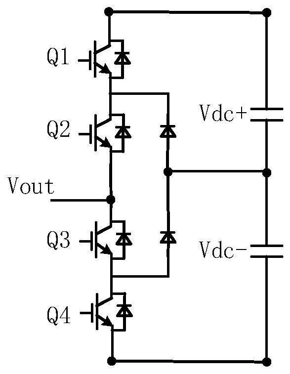
[0023] see Figure 3 to Figure 5 , image 3 It is the structural diagram of the three-level power tube of the wind power converter of the present invention; Figure 4 It is a structural diagram of the wind power converter modulator of the p...

Embodiment 2

[0027] In order to improve the bus voltage utilization ratio, the corresponding third harmonic can be injected into the grid-side reference voltage or the machine-side three-phase reference voltage in Embodiment 1. A typical injection method is assuming that the three-phase original reference voltages are respectively Vrefa ', Vrefb', Vrefc', the injected third harmonic is Vz=-0.5*max(Vrefa, Vrefb, Vrefc)-0.5*min(Vrefa, Vrefb, Vrefc), where max and min represent the maximum and minimum value, the final three-phase reference voltage is Vrefa=Vrefa'+Vz, Vrefb=Vrefb'+Vz, Vrefc=Vrefc'+Vz.

[0028] It is also possible to inject components for other purposes into the three-phase reference voltage, or to adjust the reference voltage according to other needs.


PUM


Abstract

The invention discloses a wind power converter control method, and provides a wind power converter. The wind power converter comprises a grid-side converter, a machine-side converter, a grid-side controller and a machine-side controller, wherein the grid-side controller controls the grid-side converter to adopt three-level unipolar wave generation, and the machine-side controller controls the machine-side converter to adopt three-level unipolar wave generation. According to the wind power converter control method, three-level topology direct current bus voltage ripples can be reduced, the advantages that three-level topology network side current harmonics are small, the machine side voltage du/dt and the voltage peak are small are kept, and the cost and the size of the converter are not increased. Meanwhile, the invention further discloses a power equipment control device and the converter.

Description

technical field [0001] The invention relates to the field of wind power generation, in particular to a control method for a wind power converter. Background technique [0002] The increase of single unit capacity is one of the current development trends of wind turbines. With the increase of the capacity of wind turbines, the input and output currents are getting larger and larger, which leads to the increase of cable costs and problems such as "twisted cables". In order to reduce the current, It is necessary to increase the voltage level of the motor, converter and transformer of the unit, such as increasing from the commonly used 690V to 1140V and 3300V. For the voltage level of 1140V and 3300V, the wind power converter generally adopts a three-level topology, and the three-level topology can be used Power semiconductor devices such as IGBTs with lower voltage levels can also reduce input and output current harmonics, reduce voltage du / dt and voltage spikes applied to the ...

Claims


Application Information

Patent Timeline
IPC IPC(8): H02M5/458H02M1/14H02M1/12H02M7/219H02M7/483H02M7/5395
CPCH02M5/458H02M1/14H02M1/12H02M7/219H02M7/483H02M7/5395Y02E10/76
Inventor 邹建龙周党生
Owner SHENZHEN HOPEWIND ELECTRIC CO LTD
Why Eureka
Try Eureka