Planting equipment for ecological agriculture
A technology of ecological agriculture and equipment, applied in agriculture, agricultural machinery and tools, agricultural machinery, etc., can solve the problems of slowing down the output speed of fertilizers, slowing down the speed of fertilization of crops, and splashing, so as to speed up the speed of fertilization and reduce the stickiness of soil , the effect of speeding up the output speed
- Summary
- Abstract
- Description
- Claims
- Application Information
AI Technical Summary
Problems solved by technology
Method used
Image
Examples
Embodiment 1
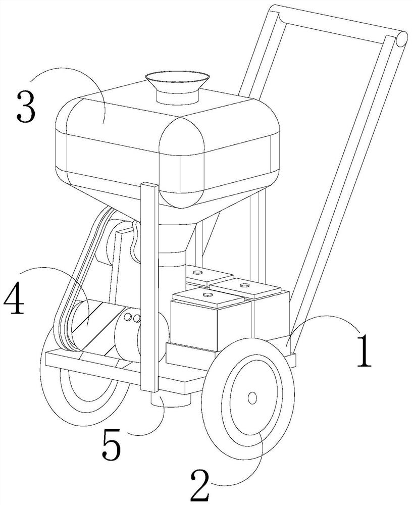
[0027] as attached figure 1 to attach Figure 5 Shown:
[0028] The present invention provides a planting equipment for ecological agriculture, the structure of which includes a body 1, a support wheel 2, a barrel 3, a motor 4, and a flow tube 5. The support wheel 2 is connected and installed on both sides of the body 1, and the barrel 3 Set above the body 1, the motor 4 is fixed above the front of the body 1, and cooperates with the support wheel 2. The flow tube 5 runs through the upper and lower surfaces of the middle of the body 1, and the top end communicates with the bottom of the barrel 3.
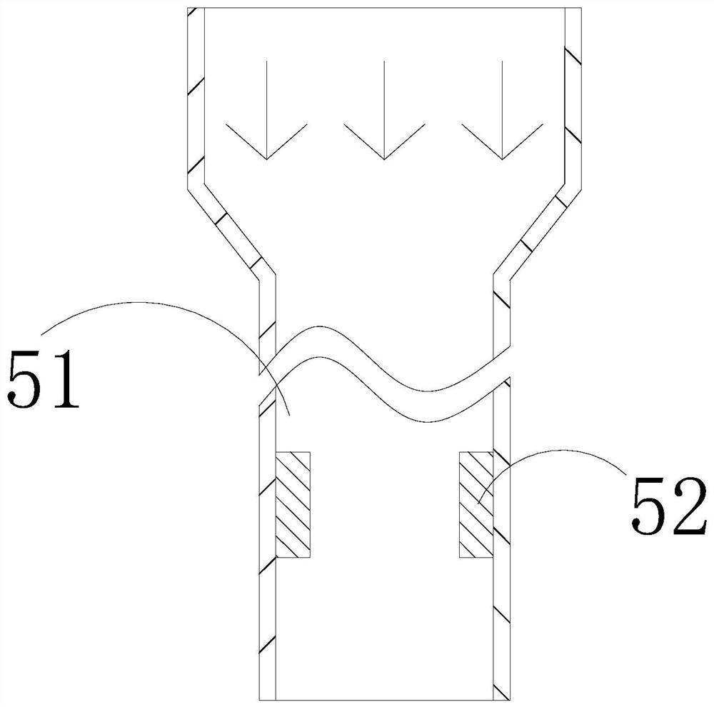
[0029] The flow pipe 5 is provided with a flow groove 51 and a pushing mechanism 52 , the flow groove 51 vertically runs through the middle part and the upper and lower surfaces of the flow pipe 5 , and the pushing mechanism 52 is fixed on the inner wall of the flow groove 51 in the middle and lower positions.
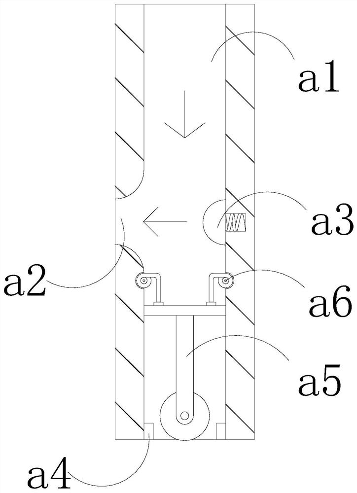
[0030] Wherein, the pushing mechanism 52 is provided with a stacking ...
Embodiment 2
[0036] as attached Image 6 to attach Figure 8 Shown:
[0037] Wherein, the limit block a4 is provided with a reverse thrust plate e1, a rebound bar e2, an inner cavity e3, a contact block e4, a support bar e5, and an exhaust hole e6, and the reverse thrust plate e1 is set on the top of the limit block a4, The rebound bar e2 is clamped between the bottom surface of the reverse thrust plate e1 and the top of the limit block a4, the inner cavity e3 passes between the left surface and the inside of the limit block a4, and the contact block e4 is sleeved in the inner cavity e3 Inside the left end, the support bar e5 is installed between the right side of the contact block e4 and the inner wall of the inner cavity e3, and the exhaust hole e6 runs through the left side and the inner side of the limit block a4, and communicates with the inner cavity e3, so The support bar e5 is made of rubber material and has elasticity, which is beneficial to push the contact block e4 to the outs...
PUM
 Abstract
Description
Claims
Application Information
 - R&D
- Intellectual Property
- Life Sciences
- Materials
- Tech Scout
- Unparalleled Data Quality
- Higher Quality Content
- 60% Fewer Hallucinations
Browse by: Latest US Patents, China's latest patents, Technical Efficacy Thesaurus, Application Domain, Technology Topic, Popular Technical Reports.
© 2025 PatSnap. All rights reserved.Legal|Privacy policy|Modern Slavery Act Transparency Statement|Sitemap|About US| Contact US: help@patsnap.com


