Method and system for emitting offset illumination for reduced stray light

Active Publication Date: 2015-06-11
PHOSEON TECHNOLOGY
View PDF9 Cites 11 Cited by
  • Summary
  • Abstract
  • Description
  • Claims
  • Application Information

AI Technical Summary

Benefits of technology

The invention aims to solve problems with conventional printing and curing systems, such as curing ink before it is applied to a substrate, and reflective light damaging the printer head. The invention proposes a method to deflect emitted light from the light source away from the printer head to reduce reflection and curing of light-curable material at the printer head. This results in faster curing times, improved system efficiency, and reduced printer head degradation.

Problems solved by technology

Accordingly, a portion of the light emitted from the light source may be reflected back onto the printer head after striking the target substrate, causing curing of the light-curable material (e.g., light-curable ink) at the printer head surface before it can be applied to the target substrate, and leading to accelerated printer head degradation.
Namely, increasing the distance of the printer head from the substrate can attenuate the irradiance of light at the substrate surface, resulting in longer curing times and lower system efficiency.
Furthermore, the use of baffles increases the cost and complexity of the apparatus setup, and the presence of baffles in the vicinity of the printer head and light source can interfere with printing reliability and light emission at the light-curable surface.

Method used


Image

  • Method and system for emitting offset illumination for reduced stray light
  • Method and system for emitting offset illumination for reduced stray light
  • Method and system for emitting offset illumination for reduced stray light

Examples


Embodiment Construction

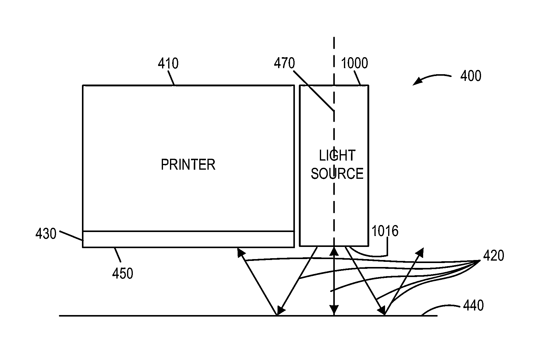
[0025]The present description relates to printer and coating system and a method of using therefor. In conventional printing and curing systems using light-curable ink, light emitted from the light source may be reflected back into the printer head after striking the target substrate, leading to curing of the ink before it can be applied to the target substrate, and printer head degradation. The inventors herein use a lens to offset or deflect the emitted light rays from a light source thereby preventing the reflected light rays from entering the print head. This configuration has the advantage of preventing the material to be cured before it reaches the target substrate.

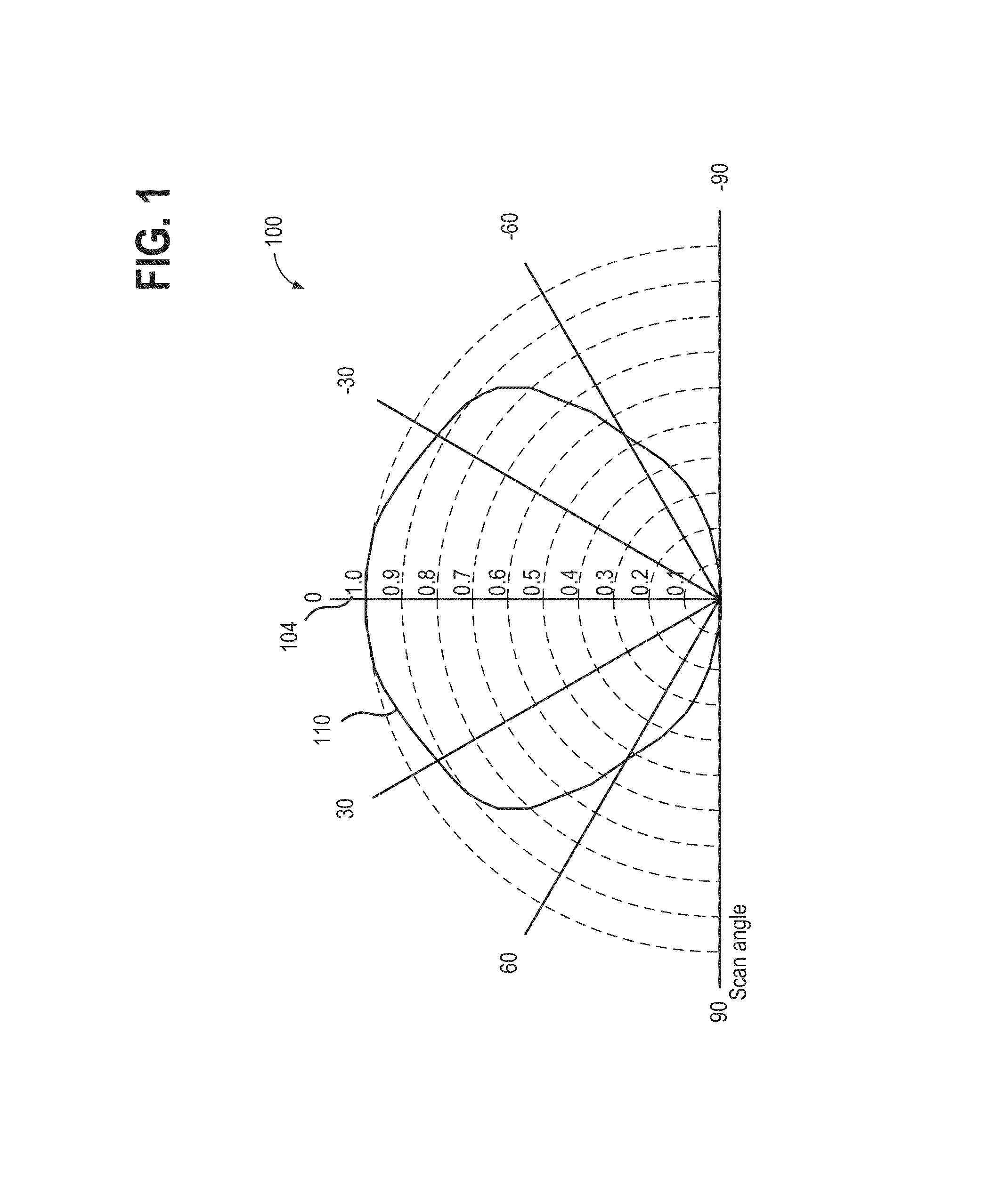
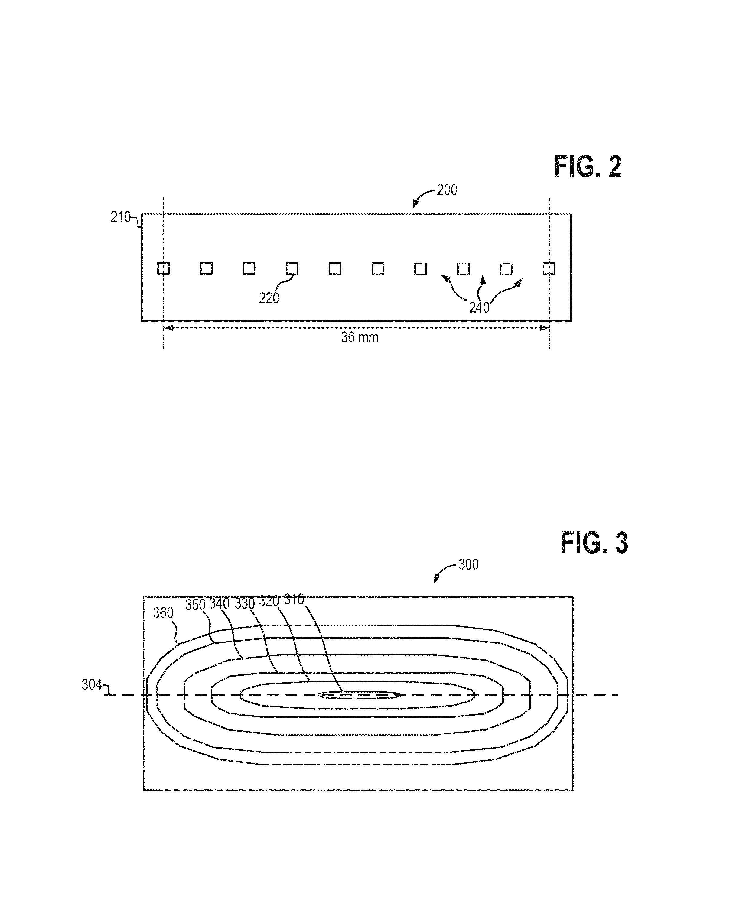
[0026]FIG. 1 illustrates an example of a near-Lambertian emission pattern for an LED light-emitting element. FIG. 2 shows a schematic depicting an example of a linear array of light-emitting elements arranged in a regularly spaced manner, and FIG. 3 illustrates an example of an irradiance pattern for the regularly s...


PUM


Abstract

A method for example of irradiating a light-curable material, may comprise irradiating light about a first axis from an array of light-emitting elements towards a light-curable surface, directing the irradiated light through an optical element interposed between the array of light-emitting elements and the light-curable surface, wherein a central axis of the optical element is offset from the first axis, and deflecting the irradiated light directed through the optical element asymmetrically away from the first axis towards the light-curable surface.

Description

CROSS-REFERENCE TO RELATED APPLICATIONS[0001]This application claims priority to U.S. Provisional Patent Application No. 61 / 912,477, entitled “METHOD AND SYSTEM FOR EMITTING OFFSET ILLUMINATION FOR REDUCED STRAY LIGHT,” filed Dec. 5, 2013, the entire contents of which are hereby incorporated by reference for all purposes.BACKGROUND AND SUMMARY[0002]Conventional printing and curing systems and methods may comprise applying and curing light-curable materials such as UV-curable ink, and the like to a substrate such as a polymer film or paper. In particular, a light-curable material, such as ink, may first be applied to the substrate via a printer head. Subsequently, the light-curable material may be cured onto the substrate using a light source. In conventional systems, the printer head is positioned adjacent to the light source so that the light-curable material may be expediently cured following application of the light-curable material onto the substrate via the printer head. Accord...

Claims


Application Information

Patent Timeline
IPC IPC(8): B41J11/00G02B27/09B41J2/165G02B27/30
CPCB41J11/002B41J2/165G02B27/0955G02B27/30F21V5/043F21V5/045B41J11/0021B41J11/00218F21V17/002G01J1/44F21W2131/403B41J2/471F21Y2103/10F21Y2115/10B41J2/47
Inventor CHILDERS, DOUG
Owner PHOSEON TECHNOLOGY
Why Eureka
Try Eureka