Method for carrying out vacuum defoaming on high-viscosity liquid by utilizing pressure difference and aerodynamic force generated by gas contained in liquid

A vacuum degassing and pressure difference technology, which is applied in liquid degassing, chemical instruments and methods, separation methods, etc., can solve the problems of degassing speed limitation, increase the complexity of degassing devices, etc., and achieve easy and efficient degassing , The system is simple and effective

Active Publication Date: 2021-06-18
悉瑞绿色电气(苏州)有限公司
View PDF27 Cites 1 Cited by
  • Summary
  • Abstract
  • Description
  • Claims
  • Application Information

AI Technical Summary

Problems solved by technology

However, if the liquid is very viscous and the bubbles are very small, it is often used to manually cut the liquid under vacuum conditions or even add power mechanical agitation to defoam, so that the volume of the bubbles increases as much as possible to expose the liquid surface and prolong the rupture time. This needs to be done in a vacuum box. The power device is placed inside, which increases the complexity of the degassing device, and the degassing speed is also limited

Method used


Image

  • Method for carrying out vacuum defoaming on high-viscosity liquid by utilizing pressure difference and aerodynamic force generated by gas contained in liquid
  • Method for carrying out vacuum defoaming on high-viscosity liquid by utilizing pressure difference and aerodynamic force generated by gas contained in liquid

Examples


Embodiment 1

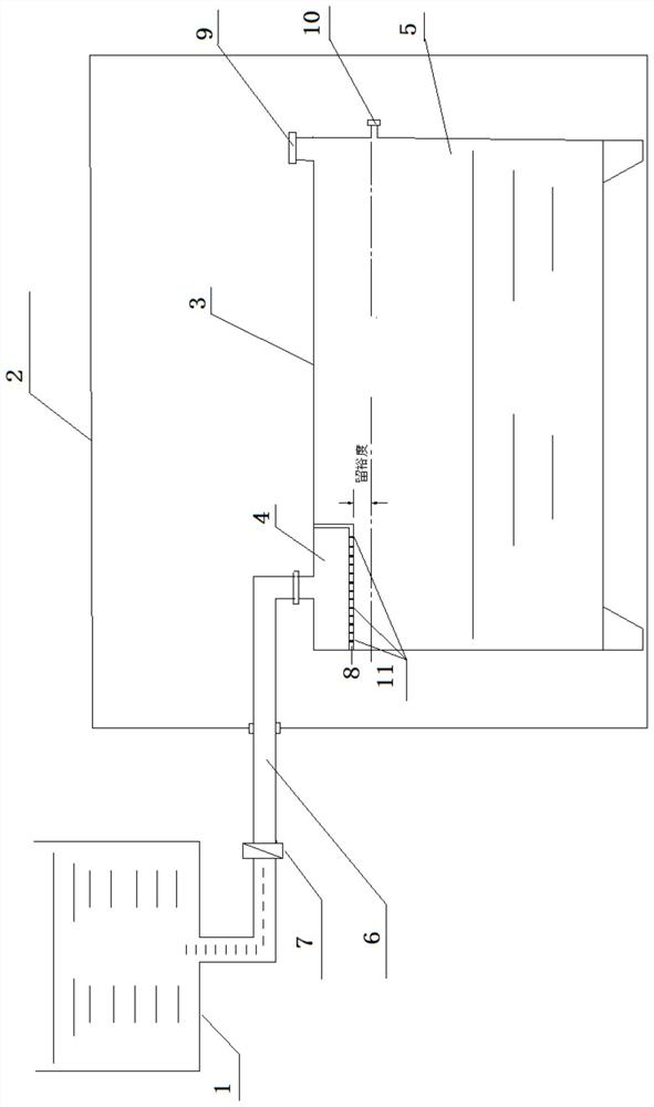
[0021] Such as figure 1 As shown, a liquid vacuum degassing system includes a hopper 1 and a vacuum box 2, and is characterized in that: a degassing container 3 is arranged in the vacuum box, and the degassing container is divided into a small chamber 4 and a large chamber 5, and the small chamber 4 Located on the top of one side of the degassing container, the top of the small chamber 4 is connected to the hopper 1 through the feeding pipeline 6, the position of the hopper is higher than the top of the small chamber, and a valve 7 is also arranged on the feeding pipeline, and the bottom of the small chamber is passed through a sieve-shaped partition 8 communicates with the large chamber of the degassing container; the degassing container is provided with a suction port 9 at the top of the other side away from the small chamber, and an overflow port 10 is provided at the upper part of the container on this side, and the position of the overflow port is lower than the sieve-shap...

Embodiment 2

[0026] This embodiment is basically the same as Embodiment 1, except that the hopper is a sealed container provided with a pressurizing device.

Embodiment 3

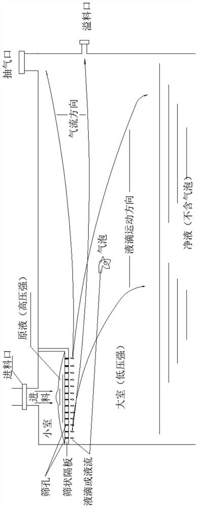
[0028] The insulating material for transformer casting is composed of two components ZS-GF-5299WA and B. It needs to be fully stirred and mixed before pouring to form a stock solution with a viscosity of about 80,000 cps. A large amount of air bubbles are mixed during the stirring process, and defoaming is required before pouring. The hopper is open, and the raw liquid slurry is pressed into the small chamber of the liquid vacuum degassing device through the manual valve by atmospheric pressure. There are 6 strip screen holes with a length of 20mm and a width of 3mm on the partition of the small chamber. The air suction port on the top is about 400mm away from the small chamber, and the overflow port is about 20mm away from the top. The maximum vacuum degree of the vacuum box is 100Pa. After vacuuming to close to 100Pa, open the valve to allow the raw liquid to enter automatically, and monitor the overflow of the overflow port. After about 15 minutes, the overflow port began ...


PUM


Abstract

The invention discloses a method for carrying out vacuum defoaming on high-viscosity liquid by utilizing pressure difference and aerodynamic force generated by gas contained in the liquid. A system is designed and comprises a hopper arranged outside a vacuum box and a defoaming container arranged in the vacuum box; the hopper is in closed connection with a feeding hole in one side of the top of a degassing container in the vacuum box and a small cutting chamber through a bottom control valve and a conveying pipe, the small chamber is communicated with a large defoaming chamber of the container through a sieve-shaped partition plate, and the large chamber is communicated with the vacuum box only through an extraction opening in the top of the other side of the container and an overflow opening in the middle of the side surface; and the overflow port is lower than the sieve-shaped partition plate. During working, the vacuum box is vacuumized, the valve is opened, the stock solution in the hopper flows through the small chamber and the large chamber under the action of pressure, and defoaming is completed under the action of aerodynamic force. An additional power device is not needed, and the whole device is simple and effective. The actual operation of defoaming the liquid with the viscosity of 50,000-120,000 cps proves that the method is effective.

Description

technical field [0001] The invention relates to a method for vacuum defoaming of high-viscosity liquid by utilizing the pressure difference and the pneumatic force generated by the gas contained in the liquid. Background technique [0002] After the liquid is stirred rapidly in the atmosphere, many air bubbles will be wrapped inside the liquid. When the viscosity is very low, the bubbles contained in the liquid in the container rely on their own buoyancy to float to the surface of the liquid. When the surface tension is not high, the bubbles burst, the gas diffuses to the environment, and the liquid sinks and gathers at the bottom of the container. So as to realize the automatic defoaming of the liquid. However, if the liquid has a high viscosity or a high surface tension, manual degassing is required. [0003] The simplest way is to adopt the vacuum static defoaming method, put the liquid containing gas in a container and put it into a vacuum box. After vacuuming, the int...

Claims


Application Information

Patent Timeline
Patent Type & Authority Applications(China)
IPC IPC(8): B01D19/00
CPCB01D19/0036
Inventor 吴济安
Owner 悉瑞绿色电气(苏州)有限公司
Why Eureka
Try Eureka