Automatic gluing production system and gluing process for motor rotor slices

A technology for motor rotors and production systems, which is applied to coatings, devices for coating liquids on surfaces, and pretreatment surfaces, etc., can solve problems such as unenvironmental protection, uneven gluing, and increase motor production costs, and achieve convenient operation, simple structure

Active Publication Date: 2021-12-07
WENLING CHAYU ELECTROMECHANICAL EQUIP FACTORY
View PDF0 Cites 0 Cited by
  • Summary
  • Abstract
  • Description
  • Claims
  • Application Information

AI Technical Summary

Problems solved by technology

[0003] However, in the existing technical solutions, the coating of the motor rotor sheet is mostly applied manually, but the coating workers have been in contact with the glue of the motor rotor lamination for a long time, which will have a certain impact on the body, and it is not environmentally friendly, and the glue is applied manually. , the gluing is uneven, which is not conducive to the assembly of the motor rotor sheet in the later stage, and the glue cannot be dried in time after the manual gluing is completed, which will easily cause the glue to be rubbed off during the handling process of the motor rotor sheet. In addition, manual gluing is not only efficient It is not high and also increases the production cost of the motor

Method used


Image

  • Automatic gluing production system and gluing process for motor rotor slices
  • Automatic gluing production system and gluing process for motor rotor slices
  • Automatic gluing production system and gluing process for motor rotor slices

Examples


Embodiment 1

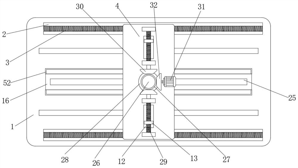
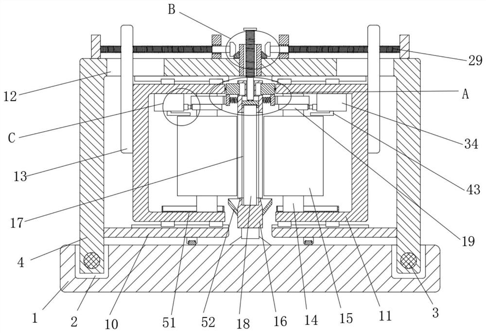
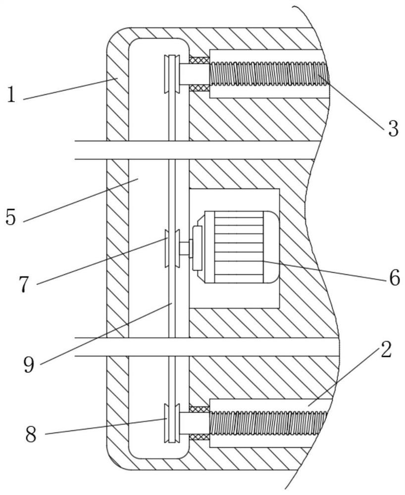
[0049] refer to Figure 1-15 , an automatic gluing production system for motor rotor slices, including a worktable 1, two symmetrical rotating grooves 2 are arranged on the top of the working table 1, and the same first U is slidably connected to the inner walls of the two sides of the two rotating grooves 2 Model plate 4, the driving assembly that is used to make the first U-shaped plate 4 move is provided in the workbench 1, and the top of the workbench 1 is fixedly connected with a placement frame 16, and the placement frame 16 is provided with a placement groove 17, and the placement groove 17 The inner wall of the bottom is provided with a rotor piece 18, the top of the first U-shaped plate 4 is provided with a fixing assembly for fixing the rotor piece 18, the top of the first U-shaped plate 4 is connected with a nut 27 for rotation, and the outer wall of the nut 27 is fixedly sleeved. A bevel gear 28, the inner walls on both sides of the first U-shaped plate 4 are fixed...

Embodiment 2

[0063] Embodiment two: if Figure 16As shown in -17, a kind of automatic gluing production system for motor rotor slices, the difference between this embodiment and Embodiment 1 is that: the top of the first U-shaped plate 4 is fixedly connected with a blower 46 and a heating box 47, and the air outlet of the blower 46 Extending in the heating box 47, the top inner wall and the bottom inner wall of the heating box 47 are equidistantly arranged with a plurality of heating pipes 48, and both sides of the heating box 47 are provided with connected air outlet pipes 49, two air outlet pipes 49 One end of each nozzle is fixedly sleeved with a nozzle 50 , and the air outlets of the two nozzles 50 are aligned with the rotor blade 18 .

[0064] However, as is well known to those skilled in the art, the working principles and wiring methods of the driving motor 6, the rotating motor 31, the blower 46 and the heating pipe 48 are commonplace, and they all belong to conventional means or c...


PUM


Abstract

The invention belongs to the technical field of motor manufacturing, in particular to an automatic gluing production system for motor rotor slices and a gluing process. The automatic gluing production system for motor rotor slices includes a workbench, and the top of the workbench is provided with two symmetrical Rotating slots, the inner walls on both sides of the two rotating slots are slidably connected with the same first U-shaped plate, and the drive assembly for moving the first U-shaped plate is provided in the workbench, and the top of the workbench It is fixedly connected with a placement frame. The structure of the present invention is simple and easy to operate. By starting the rotating motor, the clamp block and the roller brush can fix the rotor sheet, and the first U-shaped plate drives the roller brush to rotate to start coating the rotor sheet while moving. Glue, and the nozzle can dry the rotor sheet in time while the glue is being applied. There is no need for manual glue application during the glue application process, which prevents employees from long-term contact with glue, which affects their health, and improves the glue application efficiency.

Description

technical field [0001] The invention relates to the technical field of motor manufacturing, in particular to an automatic gluing production system for motor rotor slices and a gluing process. Background technique [0002] The motor is composed of a rotor core, a stator core and other accessories. The stator core is provided with a winding, and the rotor winding is placed in the rotor core slot. In order to reduce the eddy current loss generated by the core and enhance the magnetic flux density between the two poles, The rare earth rotor assembly is punched and laminated from 0.35-0.5 mm thick silicon steel sheets, and the silicon steel sheets have evenly distributed punching holes for the placement of rotor windings. The iron core silicon steel sheets used in the rotor are collectively referred to as rotor sheets. In traditional motors, the rotors are superimposed and fixed by stringing together copper cages, cast aluminum cages or other metal cages, and then assembled into ...

Claims


Application Information

Patent Timeline
Patent Type & Authority Patents(China)
IPC IPC(8): B05C1/02B05C9/14B05D3/04B05C13/02B05C11/10B05D1/28
CPCB05C1/02B05D3/0413B05C13/02B05C11/1002B05C11/1039Y02P70/10
Inventor 丁奥川
Owner WENLING CHAYU ELECTROMECHANICAL EQUIP FACTORY
Why Eureka
Try Eureka