Splicing platform

A platform and connecting block technology, applied in workbenches, manufacturing tools, etc., can solve problems such as poor structural stability, poor splicing flatness, and splicing gaps, and achieve the effects of convenient assembly and disassembly, elimination of splicing gaps, and good stability.

Pending Publication Date: 2021-06-18
四川恩巨电子科技有限公司
View PDF20 Cites 0 Cited by
  • Summary
  • Abstract
  • Description
  • Claims
  • Application Information

AI Technical Summary

Problems solved by technology

[0003] The technical problem to be solved and the technical task proposed by the present invention are to improve the existing technology, provide a splicing platform, and solve the poor structural stability of the splicing support platform in the current technology, poor splicing flatness, and splicing gaps.

Method used


Image

  • Splicing platform
  • Splicing platform
  • Splicing platform

Examples


Embodiment 1

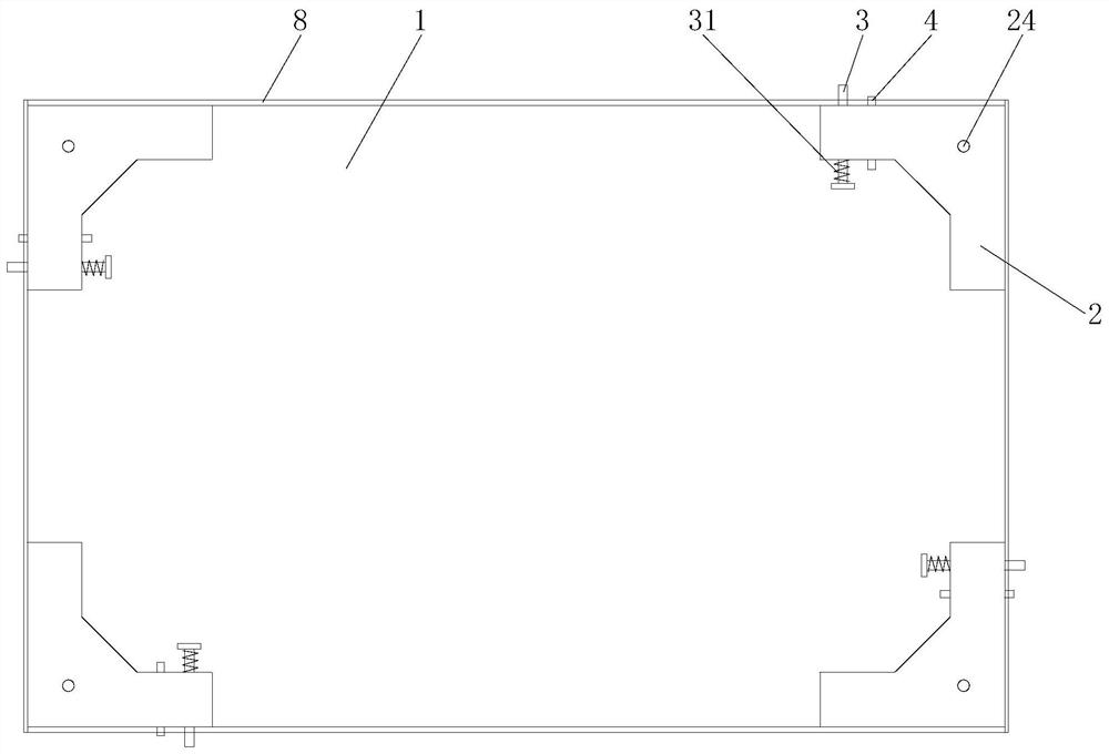
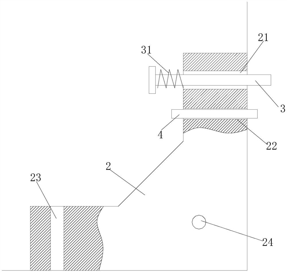
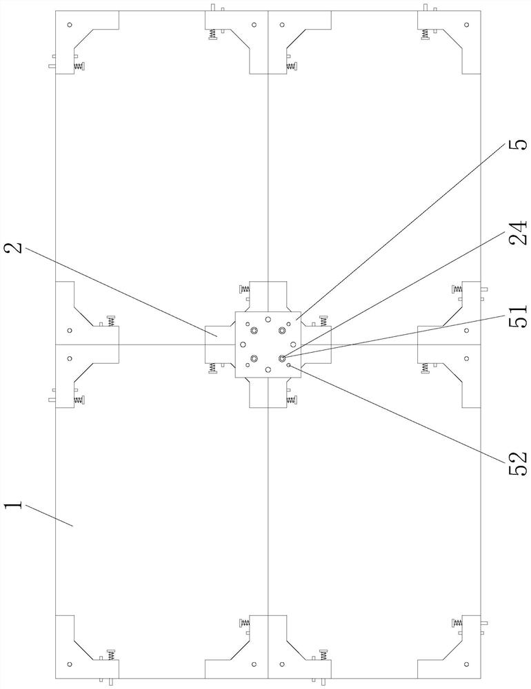
[0025] Such as Figure 1 to Figure 4 As shown, a splicing platform mainly includes a board surface 1, the board surface 1 is rectangular, the four corners of the board surface are respectively provided with connecting blocks 2, and the described connecting blocks 2 are roughly L-shaped, Along the two side edges of the corner, the connecting block 2 is provided with a first through hole 21 and a first screw hole 22 axially along the plane direction of the plate surface 1, and the first through hole and the first screw hole The axes of the holes are parallel to each other. Specifically, the first through hole and the first screw hole are located on one side of the L-shaped connecting block 2, and the axes of the first through hole and the first screw hole are perpendicular to the rectangular plate where they are located. The edge of the surface 1, the first through hole is penetrated with a first tension bolt 3 with a diameter smaller than the first through hole, and the connect...

Embodiment 2

[0032] Such as Figure 5 As shown, the difference from Embodiment 1 is that the board surface 1 is in the shape of a regular hexagon, and three board surfaces 1 are joined together at a splicing point, and the six corners of the hexagonal board surface 1 The axial directions of the first through hole and the first screw hole on the connecting block 2 are 60° in the clockwise direction, which can also ensure the stability of the splicing structure, and flexibly adjust the splicing flatness, eliminate the splicing gap, and ensure the use reliability and security.


PUM


Abstract

The invention discloses a splicing platform which comprises a plate surface. A connecting block is arranged at each corner of the plate surface, a first through hole and a first screw hole which are axially arranged along the plate surface and are parallel to each other are formed in each connecting block, a first tensioning bolt penetrates into each first through hole, a second screw hole is further formed in each connecting block, each second screw hole is used for cooperating with and being connected with the first tensioning bolt on another adjacent connecting block on the plate surface, first ejection bolts are in screw joint to the first screw holes, third screw holes perpendicular to the plate surface are formed in the connecting blocks, connecting plates are further arranged between the connecting blocks at the adjacent splicing positions of the plate surface, second through holes and fourth screw holes are formed in the connecting plates, second tensioning bolts connected with the third screw holes penetrate into the second through holes, and second ejection bolts are in screw joint to the fourth screw holes. The splicing platform is good in structural stability and convenient to assemble and disassemble and has adjusting freedom degrees in multiple directions, splicing gaps are eliminated, the overall splicing flatness is improved, and the splicing platform is more reliable and safer to use.

Description

technical field [0001] The invention relates to the technical field of support platforms, in particular to a splicing platform. Background technique [0002] In production and manufacturing, it is usually necessary to use a support platform, and use the support platform to carry out maintenance operations on large equipment. The commonly used support platform is usually a fixed structure, which takes up a lot of space and is not easy to store when it is not in use. Then there is a splicing type. support platform, but the structural stability is poor, it is difficult to guarantee the quality of the splicing, the splicing flatness is poor, and there are easy gaps at the splicing place, there are bumps and bumps when using the mobile trolley on the traditional splicing support platform, use Less secure. Contents of the invention [0003] The technical problem to be solved and the technical task proposed by the present invention are to improve the existing technology and prov...

Claims


Application Information

Patent Timeline
Patent Type & Authority Applications(China)
IPC IPC(8): B25H1/00
CPCB25H1/00
Inventor 邓恩思蔡新平李天华王萍
Owner 四川恩巨电子科技有限公司
Why Eureka
Try Eureka