Industrial autonomous moving robot with novel power assisting device

A technology of assisting device and autonomous movement, applied in manipulators, manufacturing tools, program-controlled manipulators, etc., can solve the problems of low work efficiency, difficulty in reclaiming materials, and inconvenient rotation, so as to reduce the difficulty of reclaiming materials and improve work efficiency. Efficient and easy to turn

Pending Publication Date: 2021-06-18
KUNMING UNIV OF SCI & TECH
View PDF0 Cites 0 Cited by
  • Summary
  • Abstract
  • Description
  • Claims
  • Application Information

AI Technical Summary

Problems solved by technology

It can accept human commands, and can also run according to pre-programmed programs. Modern industrial robots can also act according to the principles and guidelines formulated by artificial intelligence technology. Since the 1980s, industrial robot technology has gradually matured and has been quickly promoted. At present It has been applied in many fields of industrial production, and industrial robots have gradually been promoted and popularized. A large part of industrial robots are used in the logistics handling of manufacturing industry, which greatly promotes logistics automation. With the development of production, the performance of handling robots It has been improved and improved, but still needs to be improved in some aspects. The existing industrial robots do not have power-assisted devices to realize the autonomous movement of the robot. It is difficult to take materials, the work efficiency is low, and the rotation is not convenient enough. Problem, the present invention has designed a kind of industrial self-moving robot with novel booster

Method used


Image

  • Industrial autonomous moving robot with novel power assisting device

Examples


Embodiment Construction

[0013] The following will clearly and completely describe the technical solutions in the embodiments of the present invention with reference to the accompanying drawings in the embodiments of the present invention. Obviously, the described embodiments are only some, not all, embodiments of the present invention. Based on the embodiments of the present invention, all other embodiments obtained by persons of ordinary skill in the art without making creative efforts belong to the protection scope of the present invention.

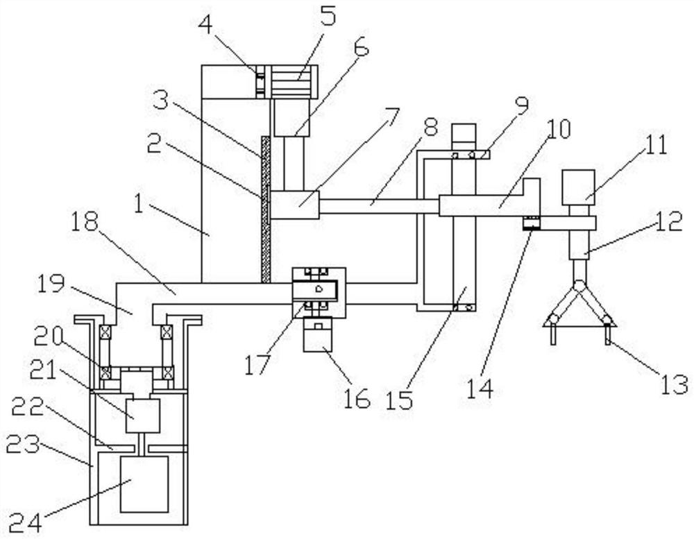
[0014] see figure 1 , the present invention provides a technical solution: including a booster 1 and a machine arm 19, the upper right side of the booster 1 is provided with a connecting buckle 4, which connects the booster 1 and the electric cylinder 5, and the right side of the connecting buckle 4 An electric cylinder 5 is provided, the lower end of the electric cylinder 5 is provided with an electric elevating rod 6, the lower end of the electric elevating ...


PUM


Abstract

The invention discloses an industrial autonomous moving robot with a novel power assisting device. The industrial autonomous moving robot comprises a power assisting table and a machine arm, wherein a connecting buckle is arranged at the upper end of the right side of the power assisting table, an electric cylinder is arranged on the right side of the connecting buckle, an electric lifting rod is arranged at the lower end of the electric cylinder, a sleeve is arranged at the lower end of the electric lifting rod, a sliding block is arranged on the left side of the sleeve, a sliding groove is formed in the left side of the sliding block, a connecting rod is arranged on the right side of the sleeve, a connector is arranged on the right side of the connecting rod, a rotating shaft is arranged at the lower end of the connector, a vertical rod is arranged on the right side of the rotating shaft, a first motor is arranged at the upper end of the vertical rod, a paw is arranged at the lower end of the vertical rod, a support is arranged on the outer side of the connector, a fixing rod is arranged on the inner side of the support, and a machine arm is arranged at the lower end of the power assisting table. According to the industrial autonomous moving robot, autonomous movement of the robot is achieved through the power assisting device, the material taking difficulty is reduced, meanwhile, the working efficiency is improved, and rotation is more convenient and faster.

Description

technical field [0001] The invention relates to the field of industrial robots, in particular to an industrial autonomous mobile robot with a novel power assist device. Background technique [0002] An industrial robot is a multi-joint manipulator or a multi-degree-of-freedom machine device for the industrial field. It can perform work automatically and is a machine that realizes various functions by its own power and control capabilities. It can accept human commands, and can also run according to pre-programmed programs. Modern industrial robots can also act according to the principles and guidelines formulated by artificial intelligence technology. Since the 1980s, industrial robot technology has gradually matured and has been quickly promoted. At present It has been applied in many fields of industrial production, and industrial robots have gradually been promoted and popularized. A large part of industrial robots are used in the logistics handling of manufacturing indus...

Claims


Application Information

Patent Timeline
Patent Type & Authority Applications(China)
IPC IPC(8): B25J9/04B25J9/12B25J15/08
CPCB25J9/04B25J9/12B25J15/08
Inventor 徐洋洋
Owner KUNMING UNIV OF SCI & TECH
Why Eureka
Try Eureka