
Automatic conveying device for welded pipe machining

An automatic conveying device and welded pipe technology, which is applied in the direction of conveyors, conveyor objects, transportation and packaging, etc., can solve the problems of manpower consumption, transmission equipment cannot carry out automatic regular transmission, confusion, etc., and achieve the effect of saving manpower

Pending Publication Date: 2021-06-18
天津市宝来工贸有限公司
View PDF0 Cites 0 Cited by
  • Summary
  • Abstract
  • Description
  • Claims
  • Application Information

AI Technical Summary

Problems solved by technology

[0002] Welded steel pipe is also called welded pipe. It is a steel pipe made of steel plate or strip steel after being crimped and welded. Generally, the length is 6 meters. The production process of welded steel pipe is simple, the production efficiency is high, there are many varieties and specifications, and the investment in equipment is small, but the general strength is low. seamless steel pipe
[0003] The existing welded pipe needs to use the transmission equipment for short-distance transmission when it is in use, but the existing transmission equipment cannot carry out automatic and regular transmission when it is in use, and it needs manual control to carry out regular transmission to prevent the transmission from being too fast. The other end of the steel pipe has not been processed. , the other has been achieved, causing confusion, and manual timing transmission needs to consume manpower, so there is an urgent need for a device to solve the above problems

Method used


Image

  • Automatic conveying device for welded pipe machining
  • Automatic conveying device for welded pipe machining
  • Automatic conveying device for welded pipe machining

Examples


Embodiment Construction

[0019] The following will clearly and completely describe the technical solutions in the embodiments of the present invention with reference to the accompanying drawings in the embodiments of the present invention. Obviously, the described embodiments are only some, not all, embodiments of the present invention. Based on the embodiments of the present invention, all other embodiments obtained by persons of ordinary skill in the art without making creative efforts belong to the protection scope of the present invention.

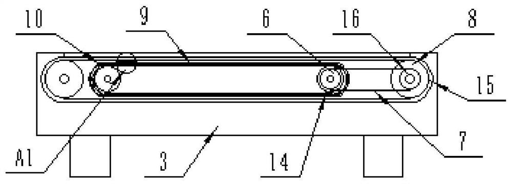
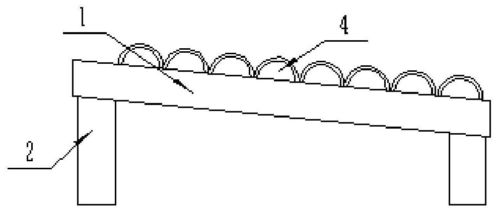
[0020] see Figure 1-5 , the present invention provides a technical solution: an automatic conveying device for welded pipe processing, including a placement box 1 and a housing 3, the lower end of the placement box 1 is welded and fixed with a support frame 2, the support frame 2 is convenient to support the entire placement box 1, and the placement box 1. The main body 4 of the welded pipe is installed inside. The left end of the placement box 1 is inclined ...


PUM


Abstract

The invention discloses an automatic conveying device for welded pipe machining. The automatic conveying device comprises a placing box and a shell, a supporting frame is fixedly arranged at the lower end of the placing box, welded pipe bodies are arranged in the placing box, the shell is arranged at the left side end of the placing box, a motor is fixedly installed on the right side of the front end of the shell, first conveying wheels are movably installed on the two sides of the interior of the shell, a first conveying belt is arranged between the outer sides of the first conveying wheels in a surrounding mode, and a first transmission wheel is fixedly installed in the center of the front end of the first conveying wheel on the right side. When an electromagnet moves to the left side position, the welded pipe body at the lower end is attracted, the welded pipe body moves to the right side to the position above the first conveying belt, transportation work is facilitated, the welded pipe body on the rear side moves to the lower end position of the placing box under the action of gravity till the electromagnet is attracted again next time, so that automatic timing transportation work is carried out, manual operation is not needed, and manpower is greatly saved.

Description

technical field [0001] The invention relates to the field of welded pipe processing equipment, in particular to an automatic conveying device for welded pipe processing. Background technique [0002] Welded steel pipe is also called welded pipe. It is a steel pipe made of steel plate or strip steel after being crimped and welded. Generally, the length is 6 meters. The production process of welded steel pipe is simple, the production efficiency is high, there are many varieties and specifications, and the investment in equipment is small, but the general strength is low. for seamless steel pipes. [0003] The existing welded pipe needs to use the transmission equipment for short-distance transmission when it is in use, but the existing transmission equipment cannot carry out automatic and regular transmission when it is in use, and it needs manual control to carry out regular transmission to prevent the transmission from being too fast. The other end of the steel pipe has not...

Claims


Application Information

Patent Timeline
Patent Type & Authority Applications(China)
IPC IPC(8): B65G47/84B65G23/22B65G59/06
CPCB65G23/22B65G47/843B65G59/068B65G2201/0276
Inventor 谢彬
Owner 天津市宝来工贸有限公司
Learn More