Shield tunneling machine steel pipe mounting and lifting device

A lifting device, shield machine technology, applied in the direction of crane, transportation and packaging, load hanging components, etc., can solve the problems of unstable clamping, difficult to install steel pipes, etc., to improve the use effect, strong adaptability, improve The effect of stability

Active Publication Date: 2021-06-18
CHINA RAILWAY 19TH BUREAU GRP RAIL TRANSIT ENG +1
View PDF5 Cites 0 Cited by
  • Summary
  • Abstract
  • Description
  • Claims
  • Application Information

AI Technical Summary

Problems solved by technology

[0003] Due to the different diameters of the pipes, the existing lifting device is likely to cause unstable clamping when clamping the pipe; and during the clamping process, the existing lifting device for the steel pipe used in the shield machine needs to be clamped To the maximum diameter of the steel pipe, it is not easy to install the steel pipe;

Method used


Image

  • Shield tunneling machine steel pipe mounting and lifting device
  • Shield tunneling machine steel pipe mounting and lifting device
  • Shield tunneling machine steel pipe mounting and lifting device

Examples


Embodiment 1

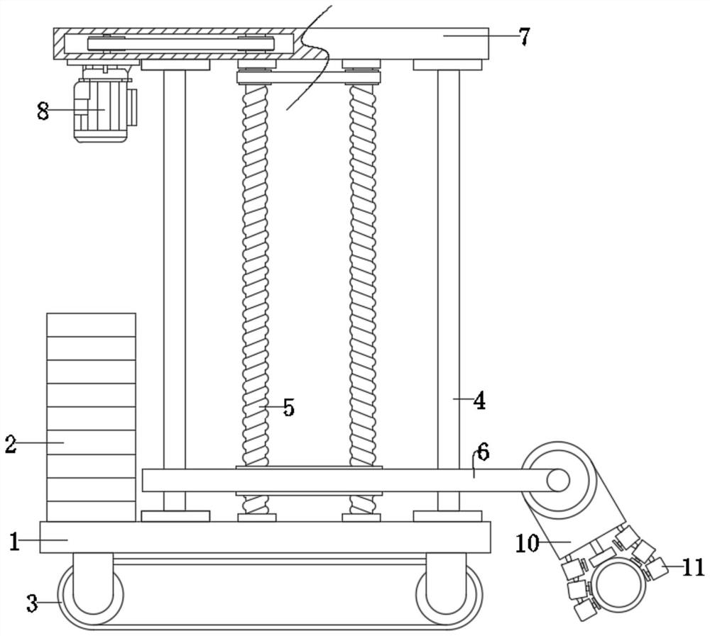
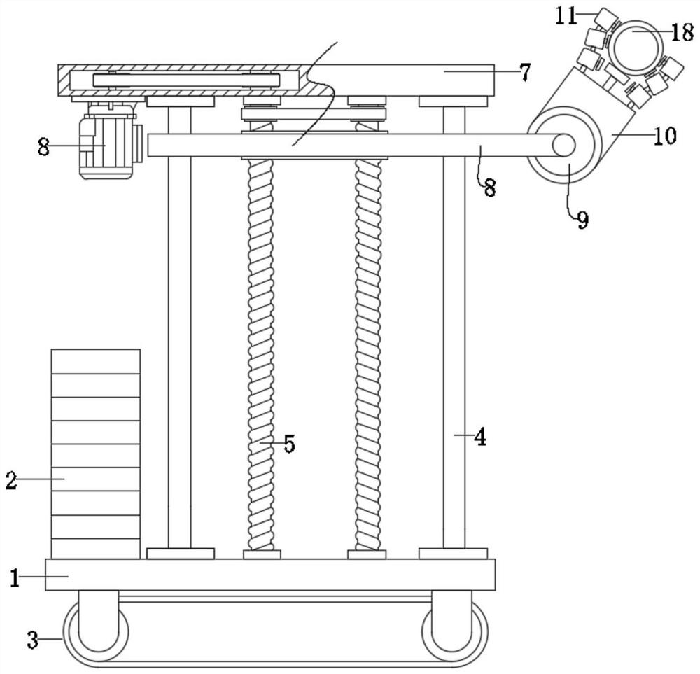
[0027] see Figure 1-3 , a steel pipe installation lifting device for a shield machine, including a bottom plate 1, an upper plate 7 and a lifting assembly, wherein a guide rod 4 is fixedly connected to the bottom plate 1, and several groups of guide rods 4 are installed on the bottom plate 1. The plate 7 is fixedly connected to the guide rod 4, and the lifting assembly is arranged and installed between the bottom plate 1 and the upper plate 7. The clamping assembly is connected and installed on the lifting assembly, and the steel pipe 18 is clamped on the clamping assembly, and the steel pipe 18 clamps Installed on the clamping assembly, the lift is performed by the lifting assembly; further, the clamping assembly includes a clamping seat 10, a clamping block 11 and an adsorption assembly, and the adsorption assembly is arranged on the clamping block 11 , the steel pipe 18 is effectively adsorbed by the adsorption assembly; the clamping block 11 is installed on the clamping s...

Embodiment 2

[0034] In this embodiment, the following improvements are made on the basis of the above embodiments, wherein a transfer assembly is arranged and installed on the base plate 1, and the transfer assembly includes rollers and crawlers 3, and the rollers are rotatably mounted on the base plate 1 and the The crawler belt 3 is swelled and installed on the rollers, and a power unit is connected to the rollers. The power unit drives the rollers to rotate, and the stability of the device during the transfer process is greatly improved under the action of the crawler belts 3 .

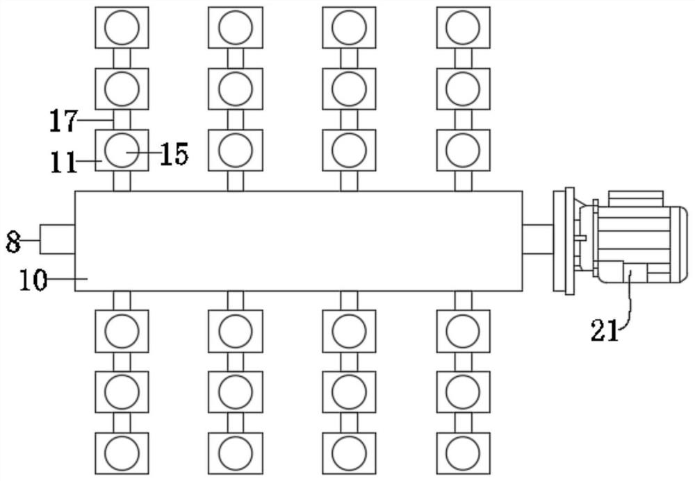
[0035]The working principle of the present invention is: during the use of the device, the adjacent clamping blocks 11 are hinged through the connecting rod 17, so that the clamping blocks 11 of a single group have certain flexibility and can adapt to different Diameter steel pipe 18; when the adsorption component on the clamping block 11 is adsorbed on the steel pipe 18, the piston rod of the telescopic rod 20 ...


PUM


Abstract

The invention discloses a shield tunneling machine steel pipe installing and lifting device which comprises a bottom plate, an upper plate and a lifting assembly, wherein the lifting assembly is arranged and installed between the bottom plate and the upper plate, a clamping assembly is connected and installed on the lifting assembly, and a steel pipe is clamped on the clamping assembly; and the clamping assembly comprises a clamping base, clamping blocks and adsorption assemblies, the adsorption assemblies are arranged on the clamping block, and the clamping blocks are installed on the clamping base. According to the device, the adjacent clamping blocks are hinged through connecting rods, so that a single group of clamping blocks has certain flexibility and can adapt to steel pipes with different diameters; when the adsorption assemblies on the clamping blocks are adsorbed on the steel pipes, a piston rod of a telescopic rod abuts against the steel pipe, and the stability in the clamping process is improved; and meanwhile, when the device lifts the steel pipe to the corresponding position, the adsorption assemblies on the two sides make contact with each other for adsorption, the steel pipe is quickly pushed and lifted to the corresponding position through the pushing and lifting effect of the telescopic rod, and the actual using effect is improved.

Description

technical field [0001] The invention relates to the field of tunnel processing, in particular to a steel pipe installation and lifting device for a shield machine. Background technique [0002] The shield machine is the main equipment for tunnel construction. During the manufacture and maintenance of the shield machine trailer, many steel pipes need to be installed and disassembled. Generally, during the installation process, each steel pipe needs to be hoisted to the top of the trailer for pressing. Tight, then a worker stands on a step ladder and secures the pipe to the top of the trailer. [0003] Due to the different diameters of the pipes, the existing lifting device is likely to cause unstable clamping when clamping the pipe; and during the clamping process, the existing lifting device for the steel pipe used in the shield machine needs to be clamped To the maximum diameter of the steel pipe, it is not easy to install the steel pipe; [0004] Furthermore, a lifting d...

Claims


Application Information

Patent Timeline
Patent Type & Authority Applications(China)
IPC IPC(8): B66C1/02B66C25/00B66C13/08B66C13/02
CPCB66C1/025B66C25/00B66C13/08B66C13/02
Inventor 马文帅黄少东白国鹏魏龙刚张光单昱桥马忠民冯永胜杨光
Owner CHINA RAILWAY 19TH BUREAU GRP RAIL TRANSIT ENG
Why Eureka
Try Eureka