Textile fabric cutting device

A technology for textiles and cutting devices, applied in the cutting of textile materials, textiles and papermaking, etc., can solve the problems of cutting offset, unqualified quality, waste, etc. Effect of contact area

Inactive Publication Date: 2021-06-18
诸暨市源浦机械科技有限公司
View PDF6 Cites 4 Cited by
  • Summary
  • Abstract
  • Description
  • Claims
  • Application Information

AI Technical Summary

Problems solved by technology

[0006] Aiming at the deficiencies of the prior art, the present invention provides a textile fabric cutting device, which solves the inconvenient operation during the cutting process, and easily causes cutting deviation, damages the fabric, causes unnecessary waste, and has a relatively high cutting thickness. When it is too large, it is easy to damage the knife, and it will cause wrinkles during the cutting process, which will easily damage the fabric and cause unqualified quality problems.

Method used


Image

  • Textile fabric cutting device
  • Textile fabric cutting device
  • Textile fabric cutting device

Examples


Embodiment 1

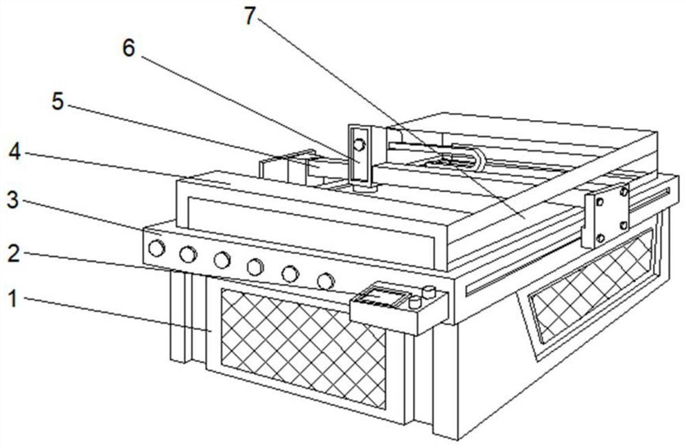
[0033] see Figure 1-2 , the present invention provides a technical solution: a textile fabric cutting device, comprising a base 1, the top of the base 1 is fixedly connected to an operating console 3, the front right side of the operating console 3 is fixedly connected to a console 2, and the top of the operating console 3 The top is fixedly connected with a protective frame 4, and the outer walls on both sides of the protective frame 4 are provided with moving grooves 7, and the middle part of the outer walls on both sides of the console 3 is provided with a driving frame 5, and the middle part of the driving frame 5 runs through the protective frame 4, and the top of the driving frame 5 A cutting device 6 is arranged on the left side of the console 3 .

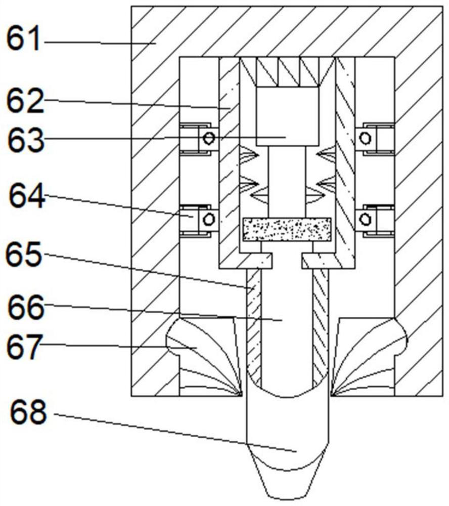
[0034] Wherein, the cutting device 6 includes a protective cover 61, the middle position of the inner cavity top of the protective cover 61 is fixedly connected with a fixed plate 62, the inner cavity top of the fixed plate...

Embodiment 2

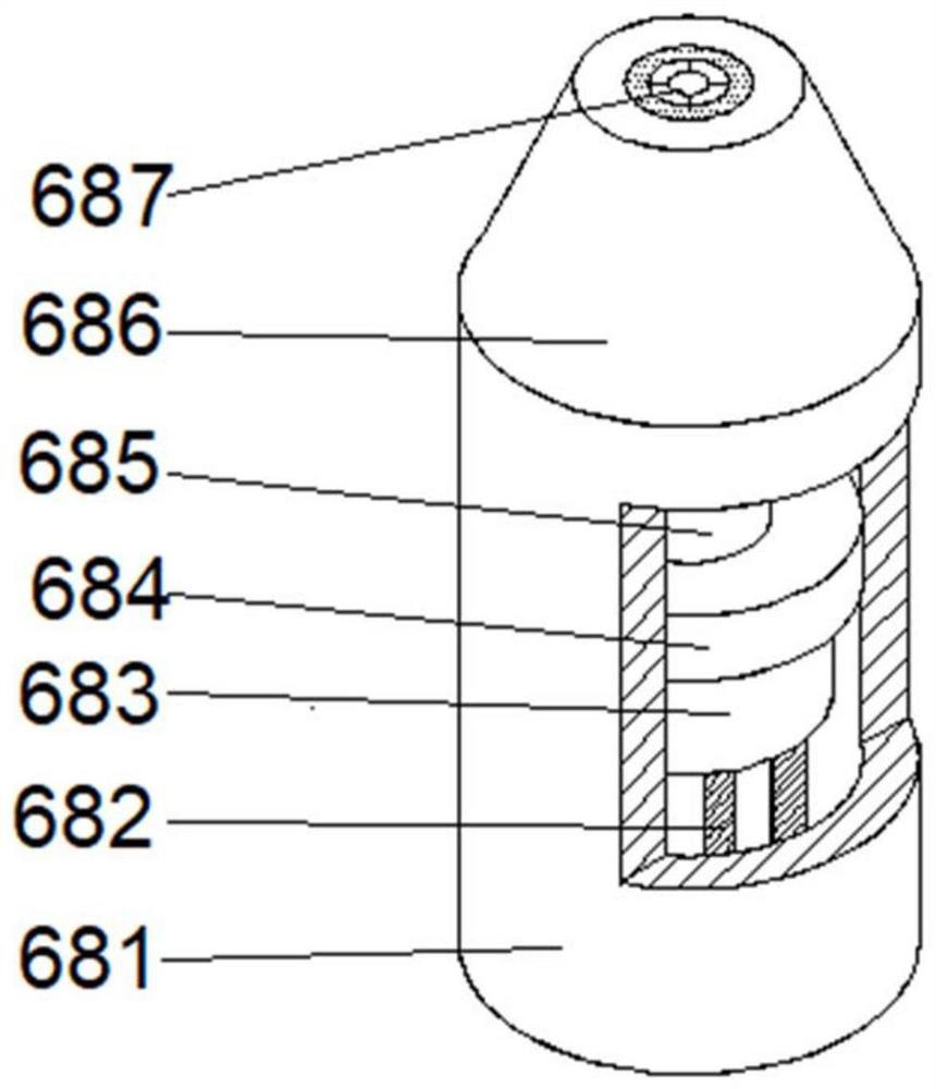
[0037] see Figure 1-3On the basis of Embodiment 1, the present invention provides a technical solution: the cutting mechanism 68 includes a main body 681, the top of the main body 681 is fixedly connected with a knife seat 686, and the middle position of the top of the base 686 is provided with a cutting knife 687, and the main body 681 A knife bar 685 is arranged at the middle position of the bottom of the inner cavity, and the top of the knife bar 685 is fixedly connected with the cutting knife 687. The middle outer surface of the knife bar 685 is provided with a fixing mechanism 684, and the bottom of the fixing mechanism 684 is fixedly connected with a sliding plate 683, and the sliding plate A rotating column 682 is provided on a side of the 683 close to the cutter bar 685 .

[0038] When in use, the cutting mechanism 68 works, and the knife bar 685 moves up and down in the main body 681, so that the sliding plate 683 and the rotating column 682 can fix the knife and the...

Embodiment 3

[0040] see Figure 1-5 , on the basis of Embodiment 1 and Embodiment 2, the present invention provides a technical solution: the fixing mechanism 684 includes a frame t1, the two sides of the top of the inner cavity of the frame t1 are fixedly connected with a linkage mechanism t2, and the outer walls of both sides of the linkage mechanism t2 The middle position is provided with a force block t3, and the middle position of the bottom of the force block t3 is provided with a movable ball t7. The two sides of the force block t3 away from the frame t1 are fixedly connected with a fixed rod t6, and the fixed rod t6 is far away from the force block t3. A bearing plate t4 is fixedly connected to one end of the bearing plate t4, and universal balls t5 are arranged on both sides of the bearing plate t4.

[0041] Among them, the linkage mechanism t2 includes a bottom block t21, and the middle position of the inner cavity top of the bottom block t21 is provided with a port t23, and the ...


PUM


Abstract

The invention discloses a textile fabric cutting device, including a base, wherein an operation table is fixedly connected to the top of the base, a control console is fixedly connected to the right side of the front face of the operation table, a protection frame is fixedly connected to the top of the operation table, moving grooves are formed in the outer walls of the two sides of the protection frame, driving frames are arranged in the middles of the outer walls of the two sides of the operation table, the middles of the driving frames penetrate through the protection frame, and a cutting device is arranged at the positions, located on the left side of the operation table, of the tops of the driving frames. The invention relates to the technical field of textile equipment. According to the textile fabric cutting device, the cutting device, a cutting mechanism, the operation table and a fixing block are arranged, the cutting mechanism moves at the bottom of the cutting device, a certain sliding space appears, the fixing block scrapes residues on the surface of the cutting mechanism, a cutter is prevented from being easily damaged when the cutting thickness is large, the situation that wrinkles are generated in a cutting process, and cloth is easy to damage is avoided, and cutting deviation is not easy to cause.

Description

technical field [0001] The invention relates to the technical field of textile equipment, in particular to a textile fabric cutting device. Background technique [0002] The textile industry has always occupied a pivotal position in my country's national economy. my country ranks first in the world in terms of production output of cotton yarn, cotton cloth, silk fabrics and clothing. [0003] According to a fabric cutting device disclosed in Chinese Patent No. CN110983744A, the thickness of the fabric is different, and the second drive rod is rotated, and the second drive rod is threaded to drive the slider to slide inside the carriage, thereby quickly adjusting the guide positioning on the slider The distance between the structure and the guiding and positioning structure on the carriage facilitates the guiding and positioning of fabrics of different thicknesses, which improves the flexibility of operation, but it is inconvenient to operate during the cutting process, and i...

Claims


Application Information

Patent Timeline
Patent Type & Authority Applications(China)
IPC IPC(8): D06H7/00
CPCD06H7/00
Inventor 罗守国
Owner 诸暨市源浦机械科技有限公司
Why Eureka
Try Eureka