Efficient energy-saving fan with compact structure

A high-efficiency energy-saving, compact structure technology, applied in the direction of supporting machines, mechanical equipment, engine frames, etc., can solve the problems of large space occupation, gas turbulence, increased fan energy loss, etc., to achieve convenient and simple maintenance, stable motor current, The effect of increasing air flow

Pending Publication Date: 2021-06-18
ZHENJIANG DANTU DISTRICT FOOD FACTORY
View PDF1 Cites 0 Cited by
  • Summary
  • Abstract
  • Description
  • Claims
  • Application Information

AI Technical Summary

Problems solved by technology

[0005] The purpose of the present invention is to provide a compact, high-efficiency and energy-saving fan, aiming to solve the conventional national standard in the prior art when transporting materials and selecting a fan for a polishing machine. The rotation speed is 2600rpm, and it is a C-type pulley drive. Compared with the A-type fan drive, the bearing box and other components are added, which brings the disadvantages of large space occupation and relatively complicated maintenance, and the existing fan is prone to accidents during operation. The turbulence between the gases leads to insufficient wind power delivered by the fan, and also increases the energy loss of the fan, and during the operation of the existing fan, the vibration generated by the motor is too large, which affects the stability of the impeller rotation , which in turn affects the efficiency of gas delivery

Method used


Image

  • Efficient energy-saving fan with compact structure
  • Efficient energy-saving fan with compact structure
  • Efficient energy-saving fan with compact structure

Examples


Embodiment

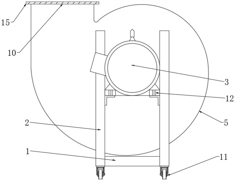
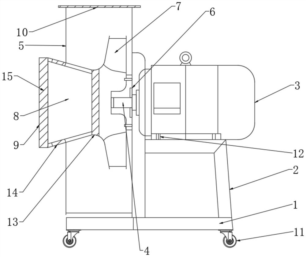
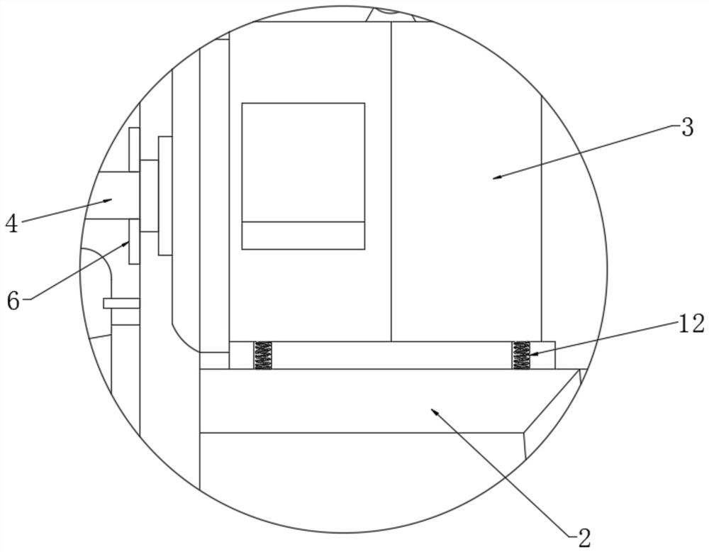
[0025] see Figure 1-6 , the present invention provides the following technical solutions: a compact high-efficiency energy-saving fan, including a fixed plate 1, the upper end of the fixed plate 1 is welded with a motor fixing seat 2, the motor fixing seat 2 is fixedly connected with a motor 3 by bolts, and the motor 3 One side is provided with an output shaft 4, and the fixed plate 1 is provided with a bellows 5 on one side of the motor 3, and one end of the output shaft 4 runs through the side wall of the bellows 5 to the inside, and the connection between the output shaft 4 and the bellows 5 is provided with Sealing gasket 6, the bellows 5 is provided with an impeller 7, the impeller 7 is fixedly connected with one end of the output shaft 4, and the impeller 7 is connected with the motor 3 through the output shaft 4, and the bellows 5 is provided with an inlet on one side of the impeller 7. Air passage 8, and the other end of air inlet passage 8 extends to the outside of b...


PUM


Abstract

The invention provides an efficient energy-saving fan with a compact structure, and belongs to the technical field of special equipment manufacturing industry. The efficient energy-saving fan with the compact structure comprises a fixing plate, a motor fixing seat is welded to the upper end of the fixing plate, a motor is fixedly connected to the motor fixing seat, an output shaft is arranged on one side of the motor, an air box is arranged on the position, located on one side of the motor, of the fixing plate, a sealing ring pad is arranged at the joint of the output shaft and the air box, an impeller is arranged in the air box and fixedly connected with one end of the output shaft, the impeller is in transmission connection with the motor through the output shaft, an air inlet channel is arranged in the position, located on one side of the impeller, of the air box, an air inlet is formed in one side of the air inlet channel, the top end of the air box is provided with an air outlet, and the bottom of the fixing plate is fixedly connected with universal wheels through bolts. The efficient energy-saving fan has the advantages of being high in efficiency, capable of saving electricity in use, capable of reducing operation cost, wide in performance range, stable in efficiency and reliable in operation, and meets the requirements for medium-and-small-distance material conveying, polishing machines, forced cooling and ventilation and dust removal system sets of parallel complex pipe networks.

Description

technical field [0001] The invention belongs to the technical field of special equipment manufacturing industry, and in particular relates to a high-efficiency and energy-saving fan with compact structure. Background technique [0002] Fan is a machine that relies on input mechanical energy to increase gas pressure and discharge gas. Ventilation of such places. [0003] The invention with the publication number CN208845388U relates to the technical field of fans, and discloses a high-efficiency and energy-saving fan with a compact structure, including a fixing seat, a round opening is opened on the front of the fixing seat, and elastic blocks are fixedly installed on the top and bottom of the round opening , the number of the elastic blocks is two, a driving motor is fixedly installed between the two elastic blocks, and sleeves are fixedly installed on both sides of the circular opening. This energy-saving fan with a compact structure is equipped with a gas dredging fan an...

Claims


Application Information

Patent Timeline
IPC IPC(8): F04D25/06F04D25/16F04D29/62F04D29/12F04D29/00F04D29/70F04D29/66F16M3/00
CPCF04D25/0606F04D25/166F04D29/002F04D29/122F04D29/624F04D29/668F04D29/703F16M3/00
Inventor 徐洋
Owner ZHENJIANG DANTU DISTRICT FOOD FACTORY
Why Eureka
Try Eureka