
Double-row planetary reducer based on friction transmission

A technology of friction transmission and double-row planets, which is applied in the direction of friction transmission, transmission, transmission parts, etc., can solve the problems of less friction reducer design, difficult preload mechanism design, limited application scenarios, etc., and achieve structural Compact, reduce design difficulty and work reliably

Active Publication Date: 2021-06-18
NINGBO INST OF MATERIALS TECH & ENG CHINESE ACADEMY OF SCI
View PDF4 Cites 0 Cited by
  • Summary
  • Abstract
  • Description
  • Claims
  • Application Information

AI Technical Summary

Problems solved by technology

In the friction wheel transmission, the traditional NGW planetary wheel arrangement is often used to balance the normal pressure exerted by the preload mechanism on the friction surfaces during the transmission process. Although this arrangement is simple in structure and reliable in operation, it is difficult Obtain a large transmission ratio, which limits its application scenarios
In the complex planetary gear train, the double-row 2K-H planetary gear train can obtain a higher transmission ratio. In addition, the preloading scheme based on the design of its planetary gear carrier can provide the friction wheel with the required positive pressure. According to the survey, there are few designs of friction reducers using this type of gear train, and the design of the preload mechanism is a difficult point

Method used


Image

  • Double-row planetary reducer based on friction transmission
  • Double-row planetary reducer based on friction transmission
  • Double-row planetary reducer based on friction transmission

Examples


Embodiment Construction

[0031] The present invention will be more fully understood from the following detailed description, which should be read in conjunction with the accompanying drawings. Detailed embodiments of the present invention are disclosed herein; however, it is to be understood that the disclosed embodiments are merely exemplary of the invention, which may be embodied in various forms. Therefore, specific functional details disclosed herein are not to be interpreted as limiting, but merely as a basis for the claims and as a teaching to one skilled in the art that, in fact, any suitably detailed embodiment may differ in any suitably detailed embodiment. The manner employs the representative basis of the present invention.

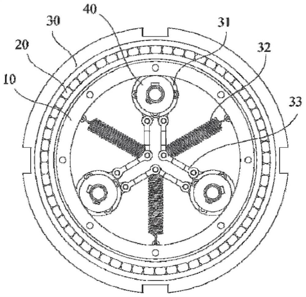
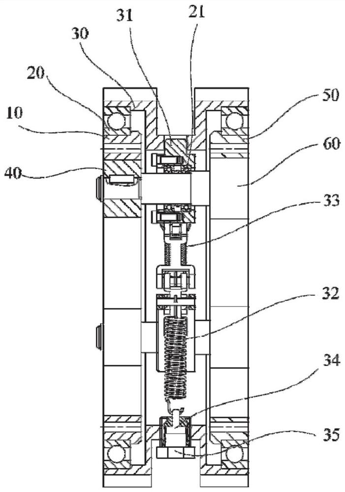
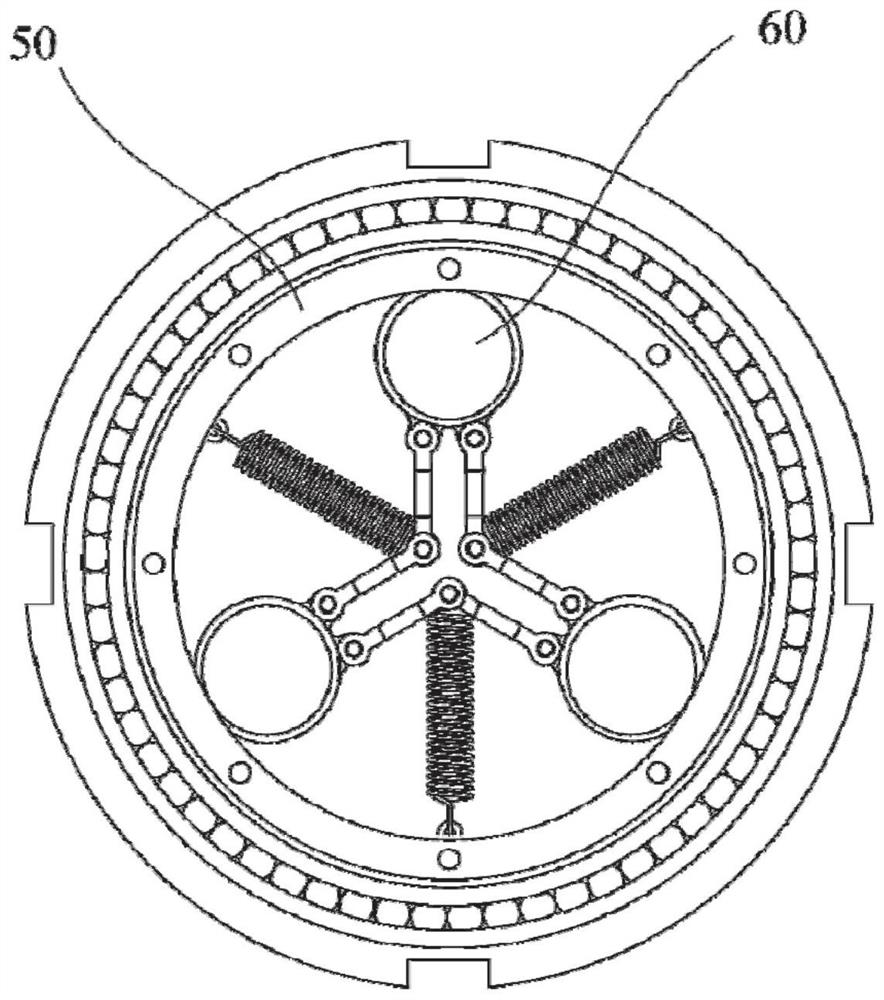
[0032] combine Figure 1 to Figure 6 As shown, a double-row planetary reducer based on friction transmission disclosed by the present invention includes a planetary carrier, a first friction rim 50, a second friction rim 10, a plurality of first planetary friction axl...


PUM


Abstract

The invention discloses a double-row planetary reducer based on friction transmission. The double-row planetary reducer comprises a planetary carrier, a first friction wheel ring, a second friction wheel ring, a plurality of first planetary friction wheel shafts and a plurality of second planetary friction wheels, the planetary carrier comprises a lantern ring and a plurality of planetary wheel bearing seats arranged on the lantern ring, the lantern ring is arranged outside the first friction wheel ring and the second friction wheel ring in a sleeving mode and rotationally connected with the first friction wheel ring and the second friction wheel ring, the second planetary friction wheel is located in the second friction wheel ring, the first planetary friction wheel shafts are located in the first friction wheel ring and penetrates through the second planetary friction wheels, each planet wheel bearing seat is rotationally connected with the corresponding first planet friction wheel shafts, each first planet friction wheel shaft is fixedly connected with the corresponding second planet friction wheels, the first friction wheel ring is fixed, the lantern ring is connected with a power source, and power of the speed reducer is input through the lantern ring and output through the second friction wheel ring. The double-row planetary reducer has the advantages of compact structure, reliable work, large transmission ratio, adjustable positive pressure and the like.

Description

technical field [0001] The invention belongs to the technical field of planetary friction reducers, and in particular relates to a double-row planetary reducer based on friction transmission. Background technique [0002] The traditional gear reducer has a transmission error caused by the tooth backlash during the forward and reverse switching process, which causes the reducer to easily cause vibration and other phenomena during the working process, resulting in poor dynamic performance; in addition, the gear design must be in accordance with The number of teeth is designed discontinuously, and the tooth matching process is cumbersome. [0003] Friction transmission is a traditional transmission method. This transmission method has a simple structure, extremely low manufacturing cost, no backlash in forward and reverse transmission, and can generate slippage when overloaded to protect parts and working objects. It is very suitable for people with It is suitable for occasion...

Claims


Application Information

Patent Timeline
Patent Type & Authority Applications(China)
IPC IPC(8): F16H13/06F16H57/08F16H57/023F16H57/021
CPCF16H13/06F16H57/082F16H57/023F16H57/021
Inventor 杨桂林杜庆皓杨淼张驰张拓璞王慰军
Owner NINGBO INST OF MATERIALS TECH & ENG CHINESE ACADEMY OF SCI
Learn More