
Clamping mechanism for high-temperature test of cartridge receiver

A high-temperature test and clamping technology, which is applied in the testing of mechanical components, the testing of machine/structural components, and measuring devices. Solve the effect of loose failure

Active Publication Date: 2021-06-18
AECC SHENYANG ENGINE RES INST
View PDF10 Cites 0 Cited by
  • Summary
  • Abstract
  • Description
  • Claims
  • Application Information

AI Technical Summary

Problems solved by technology

However, in the high-temperature test of the case, due to the influence of factors such as uneven heating of the components of the clamping mechanism and differences in the thermal expansion coefficient of materials, the clamping mechanism locked at room temperature will loosen during the heating process
In addition, since the casing test piece, the adapter barrel and the pressing mechanism must all be installed in a closed heating chamber for heating, once the clamping mechanism loosens during the heating process, it will not be able to perform secondary locking, resulting in the failure of the clamping mechanism. fail
Therefore, this structure is not suitable for casing high temperature test

Method used


Image

  • Clamping mechanism for high-temperature test of cartridge receiver
  • Clamping mechanism for high-temperature test of cartridge receiver
  • Clamping mechanism for high-temperature test of cartridge receiver

Examples


Embodiment Construction

[0041] In order to make the purpose, technical solution and advantages of the application more clear, the technical solution in the embodiment of the application will be described in more detail below in conjunction with the drawings in the embodiment of the application. In the drawings, the same or similar reference numerals denote the same or similar elements or elements having the same or similar functions throughout. The described embodiments are some, but not all, embodiments of the application. The embodiments described below by referring to the figures are exemplary, and are intended to explain the present application, and should not be construed as limiting the present application. Based on the embodiments in this application, all other embodiments obtained by persons of ordinary skill in the art without creative efforts fall within the protection scope of this application. Embodiments of the present application will be described in detail below in conjunction with th...


PUM


Abstract

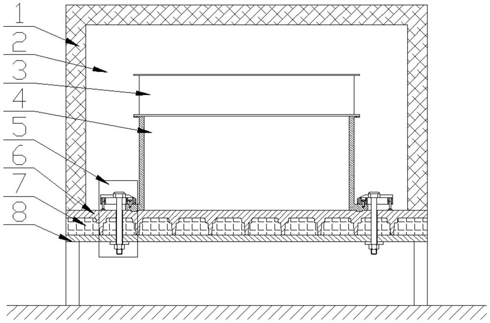
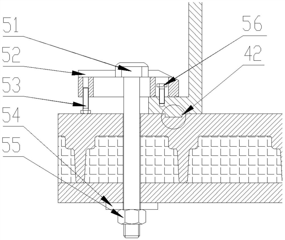
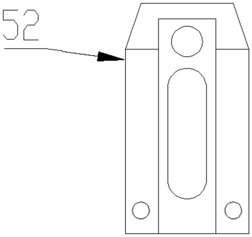
The invention belongs to the field of aero-engine tests, and particularly relates to a clamping mechanism for a high-temperature test of a cartridge receiver. The clamping mechanism comprises a base, a faceplate, a heat preservation cover, an adapter cylinder and a cartridge receiver test piece. The faceplate is fixedly mounted on the base, a gap is formed between the faceplate and the base, and the gap is filled with a thermal insulation material; the heat preservation cover is arranged on the faceplate, and a heating cavity is defined by the heat preservation cover and the faceplate; the adapter cylinder is contained in the heating cavity, the adapter cylinder is provided with an upper mounting edge and a lower mounting edge, and the lower mounting edge is connected with the faceplate through an axial positioning assembly, a radial positioning structure and a circumferential positioning assembly; the cartridge receiver test piece is accommodated in the heating cavity, and the cartridge receiver test piece is connected with the upper mounting edge of the adapter cylinder. According to the clamping mechanism, effective locking of the cartridge receiver adapter cylinder can be achieved in the high-temperature environment, the secondary locking function is achieved, and the problem that an existing clamping mechanism is loosened and fails in the heating process is effectively solved.

Description

technical field [0001] The application belongs to the field of aero-engine testing, and in particular relates to a clamping mechanism for casing high-temperature testing. Background technique [0002] For aero-engine casing components that work at high temperatures for a long time, such as the turbine rear casing, a series of static and fatigue tests need to be carried out during the development process. In order to better simulate the actual working environment of the casing, this type of Tests often need to be carried out in a high temperature environment. [0003] During the test, the casing test piece needs to be clamped and fixed on the test platform so that it does not move or rotate under the test load. At present, the casing test piece is connected to the upper mounting edge of the adapter barrel through bolts and nuts; the lower mounting edge of the adapter barrel has a U-shaped groove, which is pressed and fixed by a compression mechanism composed of anchor bolts,...

Claims


Application Information

Patent Timeline
Patent Type & Authority Applications(China)
IPC IPC(8): G01M13/00
CPCG01M13/00
Inventor 刘韬霍成民王洪斌刘伟强
Owner AECC SHENYANG ENGINE RES INST
Learn More