
A Simulation Method of Wall Surface Temperature in Anti-icing System

A technology of anti-icing system and simulation method, applied in the direction of design optimization/simulation, calculation, computer-aided design, etc., can solve the problems of increasing calculation workload and complexity, ignoring the temperature gradient of surface film, and being difficult to analyze with anti-icing system , to achieve the effect of reducing the workload and complexity of the algorithm, reducing the workload of the algorithm, and reducing the complexity

Active Publication Date: 2021-08-03
LOW SPEED AERODYNAMIC INST OF CHINESE AERODYNAMIC RES & DEV CENT
View PDF7 Cites 0 Cited by
  • Summary
  • Abstract
  • Description
  • Claims
  • Application Information

AI Technical Summary

Problems solved by technology

[0008] 1. The convergence calculated by using the simulation method of separating the inside and the outside depends heavily on the assumption of the initial temperature or initial heat flow of the wall. Once the assumed initial temperature and initial heat flow deviate greatly from the real data, the entire iterative process will not converge;
[0009] 2. The existing simulation method ignores the temperature gradient of the surface film along the height direction, and thinks that the temperature at the bottom and top of the surface film is the same. However, under real conditions, there is a temperature difference between the upper and lower surfaces of the surface film, so heat can be transferred, although it can achieve anti-icing The simple analysis before the design of the system is difficult to be used for the complete analysis of the anti-icing system, which reduces the accuracy of the simulation;
[0010] The simulation of the existing method needs to establish two sets of grids, and divide the internal dry air flow field and the external dry air flow field separately, which increases the workload and complexity of the calculation, and has the problem of low calculation efficiency

Method used

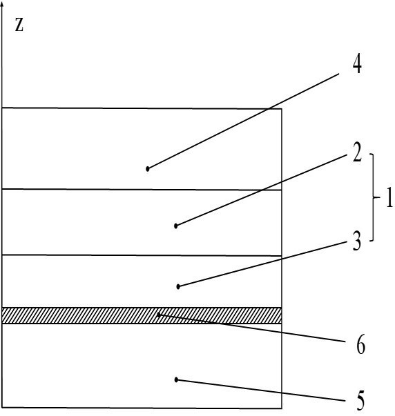
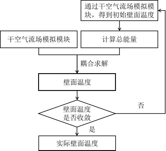
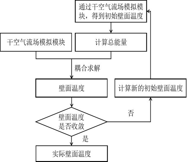

Image

  • A Simulation Method of Wall Surface Temperature in Anti-icing System
  • A Simulation Method of Wall Surface Temperature in Anti-icing System
  • A Simulation Method of Wall Surface Temperature in Anti-icing System

Examples


Embodiment Construction

[0035] The following description provides many different embodiments, or examples, for implementing various features of the invention. The elements and arrangements described in the following specific examples are only used to express the present invention in a concise manner, and are only used as examples rather than limiting the present invention.

[0036] Aspects of the invention will be described more fully hereinafter with reference to the accompanying drawings. This invention may, however, be embodied in many different forms and should not be construed as limited to any specific structure or function presented throughout this invention. Rather, these aspects are provided so that this disclosure will be thorough and complete, and will fully convey the scope of the invention to those skilled in the art. Based on the teachings herein one skilled in the art will appreciate that the scope of the invention is intended to encompass any aspect disclosed herein, whether implemen...


PUM


Abstract

The present invention is applicable to the field of anti-icing technology, and provides a method for simulating the wall surface temperature of an anti-icing system. Mesh division is consistent; the initial wall temperature is obtained through the dry air flow field simulation module T s 0 ;Through the i‑1th wall temperature T s i‑1 Calculate the total energy of the surface film Q i‑1 , by dividing the total surface film energy Q i‑1 Substitute into the dry air flow field simulation module to obtain the i-th wall temperature T s i ;Judging the i-th wall temperature T s i Convergence; if the i-th wall temperature T s i does not converge, then let i=i+1 , repeat the above steps; if the i-th wall temperature T s i Convergence, that is, the i-th wall temperature T s i is the final wall temperature. The invention provides a wall surface temperature simulation method with good convergence, convenient solution and closer to the real physical process.

Description

technical field [0001] The invention belongs to the technical field of anti-icing and in particular relates to a method for simulating the wall surface temperature of an anti-icing system. Background technique [0002] The formation of icing on the surface of aerospace vehicles in the air is very harmful. It not only increases the weight of the aerospace vehicle, but also destroys the aerodynamic shape of the aerospace vehicle, increases the resistance of the aerospace vehicle, leads to a decrease in maneuverability and stability, and may cause severe damage. accident. The existing icing protection systems of aerospace vehicles are divided into two categories: one is the anti-icing system, that is, the system that does not allow ice to form on aerospace components; the other is the deicing system, that allows If there is a small amount of ice on the surface, then perform periodic deicing. [0003] The hot gas anti-icing method is to draw high-temperature and high-pressure ...

Claims


Application Information

Patent Timeline
Patent Type & Authority Patents(China)
IPC IPC(8): G06F30/28G06F30/23G06F119/08
CPCG06F30/23G06F30/28G06F2119/08
Inventor 陈宁立易贤王强刘宇
Owner LOW SPEED AERODYNAMIC INST OF CHINESE AERODYNAMIC RES & DEV CENT
Learn More