Spraying equipment capable of changing spraying angle
A technology of spraying equipment and spraying angle, applied in the direction of spraying device, etc., can solve the problems of low efficiency, complicated process, incomplete spraying of steel pipes, etc., and achieve the effect of uniform spraying layer
- Summary
- Abstract
- Description
- Claims
- Application Information
AI Technical Summary
Problems solved by technology
Method used
Image
Examples
Embodiment 1
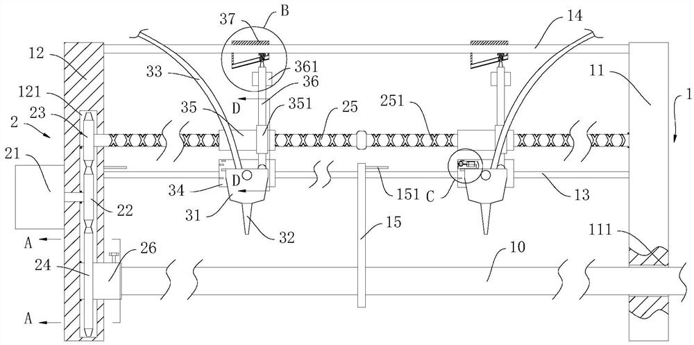
[0029] Such as Figure 1 to Figure 8As shown, a spraying equipment capable of changing the spraying angle provided by the embodiment of the present invention includes a steel pipe 10, a supporting device 1, a driving device 2 and a spraying device 3, and the supporting device 1 includes a first support plate 11 and a second support plate 12 , the first guide rod 13 and the second guide rod 14, the first support plate 11 and the second support plate 12 are fixedly connected to the ground, the first support plate 11 is provided with a first cavity 121 inside, and the second support plate 12 The plate 12 is provided with a first through hole 121, the first through hole 121 is matched with the steel pipe 10, the two ends of the first guide rod 13 are respectively fixedly connected to the first support plate 11 and the second support plate 12, the second The two ends of the two support plates 12 are respectively fixedly connected to the first support plate 11 and the second support...
Embodiment 2
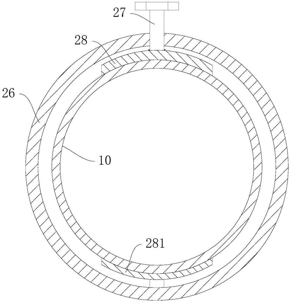
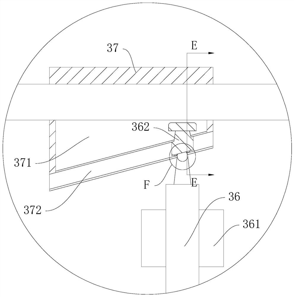
[0038] On the basis of Example 1, such as Figure 1 to Figure 8 As shown, the clamping device includes a bolt 27, a first clamping block 28 and a second clamping block 281, the second clamping block 281 is fixedly connected to the lower end of the inner wall of the connecting sleeve 26, and the bolt 27 passes through the upper end of the connecting sleeve 26 and is connected to the upper end of the connecting sleeve 26. The first clamping block 28 is rotatably connected to the bolt 27 through thread fit. The adjusting device includes a third sleeve 351, a connecting rod 36 and an adjusting block 37. The third sleeve 351 is rotatably connected to the second sleeve 35, and the connecting rod 36 is sleeved on the third sleeve 351. The connecting rod 36 One end of one end is hinged on one side of the upper end of the spraying pump 31, and the adjusting block 37 is slidably connected to the second guide rod 14, and a second cavity 371 is opened in the adjusting block 37, and a slid...
PUM
 Abstract
Description
Claims
Application Information
 - R&D
- Intellectual Property
- Life Sciences
- Materials
- Tech Scout
- Unparalleled Data Quality
- Higher Quality Content
- 60% Fewer Hallucinations
Browse by: Latest US Patents, China's latest patents, Technical Efficacy Thesaurus, Application Domain, Technology Topic, Popular Technical Reports.
© 2025 PatSnap. All rights reserved.Legal|Privacy policy|Modern Slavery Act Transparency Statement|Sitemap|About US| Contact US: help@patsnap.com


