
Welding device and welding method for steel pipe pile shear ring

A technology for welding devices and steel pipe piles, applied in auxiliary devices, welding equipment, welding equipment, etc., can solve the problems of low welding efficiency and poor welding quality of shear rings, and achieve the effect of improving welding quality and welding efficiency

Active Publication Date: 2021-06-22
GUANGZHOU WENCHUAN HEAVY IND
View PDF7 Cites 1 Cited by
  • Summary
  • Abstract
  • Description
  • Claims
  • Application Information

AI Technical Summary

Problems solved by technology

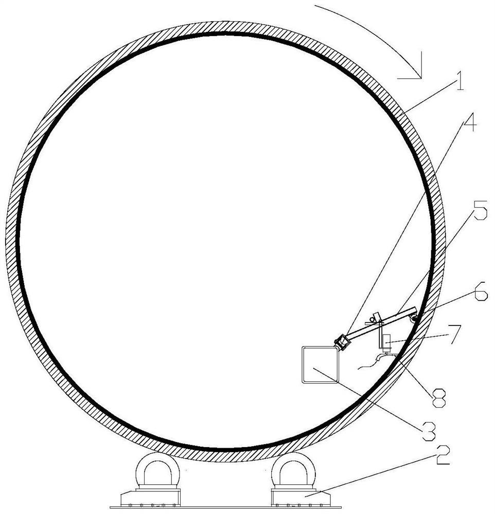
[0003] The purpose of the present invention is to overcome the deficiencies in the prior art, and provide a welding device for steel pipe pile shear rings, which can solve technical problems: the technical problem solved is that the welding efficiency of steel pipe pile shear rings for offshore wind power stabilization piles is low, and the welding The problem of poor quality, the purpose is to use the advantages of semi-automatic welding to improve the welding efficiency of the steel pipe pile shear ring and improve the welding quality of the shear ring without increasing the large cost

Method used


Image

  • Welding device and welding method for steel pipe pile shear ring
  • Welding device and welding method for steel pipe pile shear ring
  • Welding device and welding method for steel pipe pile shear ring

Examples


Embodiment Construction

[0028] The specific implementation manners of the present invention will be further described in detail below in conjunction with the accompanying drawings and embodiments. The following examples are used to illustrate the present invention, but are not intended to limit the scope of the present invention.

[0029] In the description of the present invention, it should be understood that the orientation or positional relationship indicated by the terms "upper", "lower", "left", "right", "top", "bottom" etc. Orientation or positional relationship is only for the convenience of describing the present invention and simplifying the description, and does not indicate or imply that the referred device or element must have a specific orientation, be constructed and operated in a specific orientation, and thus should not be construed as a limitation of the present invention. It should be understood that the terms "first", "second", etc. are used in the present invention to describe va...


PUM

PropertyMeasurementUnit
diameteraaaaaaaaaa

Abstract

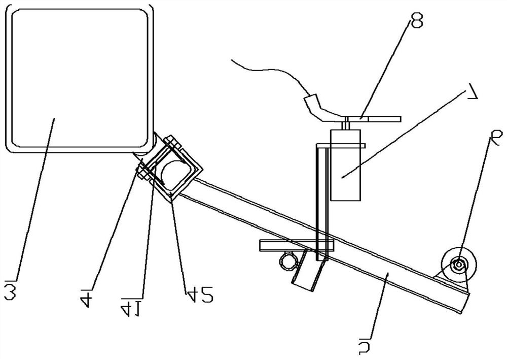
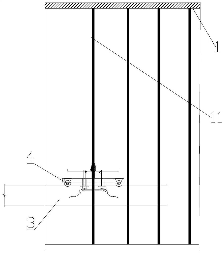
The invention discloses a welding device and a welding method for a steel pipe pile shear ring. The welding device is used for a steel pipe pile which is horizontally arranged on a roller frame in a rolling manner, and comprises a supporting beam which horizontally penetrates through the steel pipe pile, wherein supporting bases which are fixed on the ground are arranged at the two ends of the supporting beam; a travelling trolley which moves in the axial direction of the steel pipe pile is arranged on the supporting beam; a positioning part which can swing in the axial direction of the steel pipe pile is mounted on the travelling trolley; the positioning part extends towards the inner wall of the steel pipe pile; the end part of the positioning part is equipped with a roller which rotatably abuts against the inner wall of the steel pipe pile; a swinging device which can swing in the axial direction of the steel pipe pile is arranged on the positioning part; and a welding gun which faces towards the inner wall of the steel pipe pile is mounted on the swinging device. The welding device for the steel pipe pile shear ring can improve welding efficiency of the steel pipe pile shear ring, and improves welding quality of the shear ring.

Description

technical field [0001] The invention relates to the technical field of offshore wind power equipment, in particular to a welding device and a welding method for a steel pipe pile shear ring. Background technique [0002] In offshore wind power projects, there are shear ring accessories on the top of the pile. The length of the shear ring on the top of the pile is about 6 meters, including a total of 21 rings, and the range of the shear ring at the bottom of the pile is 8 meters, including a total of 13 rings. The shear ring is The round steel, the shear ring and the pile wall are welded in the form of double-sided fillet welds. The diameter of the pile group is about 2400mm, and the workload of welding the shear ring in a single pile group is as high as 498 meters. The steel pipe pile is generally a round pipe with a diameter of about 2.5m and a length of about 70 meters. The welding of the shear ring on the steel pipe pile The length is about 10m. At present, manual weld...

Claims


Application Information

Patent Timeline
Patent Type & Authority Applications(China)
IPC IPC(8): B23K31/02B23K37/02B23K37/053
CPCB23K37/053B23K37/0247B23K37/0294B23K31/02
Inventor 徐朝阳龙盛根向国正王川江陈世明吴智财钟志锋邓荡涤王月英
Owner GUANGZHOU WENCHUAN HEAVY IND
Learn More