Air purifier shell filtering hole forming machining device

An air purifier and forming technology, applied in metal processing and other directions, can solve the problems of low forming efficiency of casing filter holes, non-circular forming of casing filter holes, deviation of hole size, etc., achieving good fixing effect, convenient collection of casings, The effect of preventing shell breakage

Inactive Publication Date: 2021-06-22
王晓寅
View PDF8 Cites 2 Cited by
  • Summary
  • Abstract
  • Description
  • Claims
  • Application Information

AI Technical Summary

Problems solved by technology

[0003] Today's air purifiers generally use a shell made of engineering plastics such as ABS. Inside the shell are set fans, motors, aluminum and other internal components. The shell is often equipped with hole-shaped air inlets and air outlets. The motor drives the fan. The air is sucked through the filter material, and the pollution particles such as pm2.5 contained in the air are absorbed by the filter material, so that the air becomes clean after passing through the filter material, and then is discharged into the room from the air outlet, thereby gradually purifying the indoor air circulation; For the forming process of the filter hole on the shell of the air purifier, the forming process is carried out by punching. During the forming process, there is no good pre-fixation, and then the punching process is performed, resulting in the shape of the filter hole on the shell is not circular, so that There are deviations in the hole size, resulting in more burrs, and it is easy to cause the shell to be damaged due to excessive pressing force during pressing and fixing, resulting in increased production costs, and it is necessary to manually collect and take the punched shell, causing the shell to be damaged. The filter hole forming efficiency is low; for this reason, the invention provides a filter hole forming processing device for the housing of an air cleaner

Method used


Image

  • Air purifier shell filtering hole forming machining device
  • Air purifier shell filtering hole forming machining device
  • Air purifier shell filtering hole forming machining device

Examples


Embodiment Construction

[0026] The embodiments of the present invention will be described in detail below with reference to the accompanying drawings, but the present invention can be implemented in many different ways defined and covered by the claims.

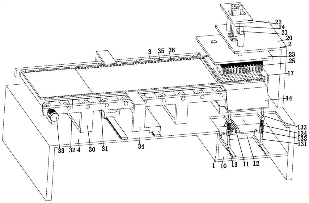
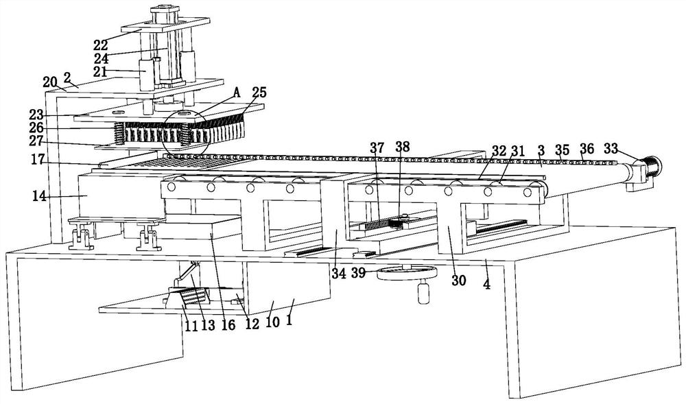
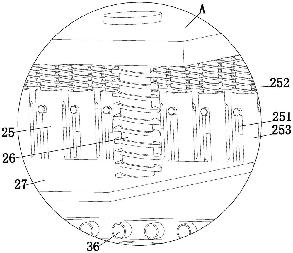
[0027] Such as Figure 1 to Figure 8 As shown, an air purifier shell filter hole forming processing device includes a discharge mechanism 1, a stamping mechanism 2, a conveying mechanism 3 and a main beam support 4, and the conveying mechanism 3 and the stamping mechanism are respectively installed on the main beam support 4 2. A discharge mechanism 1 is provided between the conveying mechanism 3 and the stamping mechanism 2. The discharge mechanism 1 is installed on the main beam support 4, and the discharge mechanism 1 is located directly below the stamping mechanism 2, wherein:

[0028] The discharge mechanism 1 includes an L-shaped bottom plate 10, a push cylinder 11, a push carriage 12, a lifting control unit 13, a platform bracket 14, a discha...


PUM


Abstract

The invention provides an air purifier shell filtering hole forming machining device which comprises a discharging mechanism, a stamping mechanism, a conveying mechanism and a main beam support, the conveying mechanism and the stamping mechanism are installed on the main beam support, the discharging mechanism is arranged between the conveying mechanism and the stamping mechanism, and the discharging mechanism is mounted on the main beam support. The air purifier shell filtering hole forming machining device solves the problems that the filter holes in the shell of the air purifier are formed in a blanking manner at present, and are not well fixed in advance and then punched in the forming process, so that the filter holes of the shell are formed in a non-circumferential manner, the hole pattern size is deviated, more burrs are caused, in addition, the shell is prone to being damaged due to too large pressing force in the pressing and fixing process, the production cost is increased, the punched shell needs to be manually collected and taken, and the shell filtering hole forming efficiency is low.

Description

technical field [0001] The invention relates to the technical field of forming filter holes of an air purifier shell, in particular to a filter hole forming processing device for an air purifier shell. Background technique [0002] Air purifiers, also known as "air cleaners", air fresheners, and purifiers, refer to products that can absorb, decompose or transform various air pollutants and effectively improve air cleanliness. They are mainly divided into household, commercial, industrial, and building ; [0003] Today's air purifiers generally use a housing made of engineering plastics such as ABS. Inside the housing are set fans, motors, aluminum and other internal components. The housing is often equipped with hole-shaped air inlets and outlets. The motor drives the fan. The air is sucked through the filter material, and the pollution particles such as pm2.5 contained in the air are absorbed by the filter material, so that the air becomes clean after passing through the f...

Claims


Application Information

Patent Timeline
Patent Type & Authority Applications(China)
IPC IPC(8): B26F1/14B26D7/02B26D7/06B26D7/18B26D7/32
CPCB26F1/14B26D7/02B26D7/0625B26D7/18B26D7/32
Inventor 王晓寅马双斌王小婷
Owner 王晓寅
Why Eureka
Try Eureka