
Conveying device

A technology of conveying device and conveying assembly, which is applied in the direction of conveyor control device, transportation and packaging, conveyor objects, etc., can solve the problem of high cost and achieve the effect of easy installation and disassembly, reducing errors and low cost

Active Publication Date: 2021-06-22
HANS LASER TECH IND GRP CO LTD +1
View PDF13 Cites 0 Cited by
  • Summary
  • Abstract
  • Description
  • Claims
  • Application Information

AI Technical Summary

Problems solved by technology

[0003] At present, most of the precision transmission platforms on the market use complex transmission mechanisms, resulting in high overall cost

Method used


Image

  • Conveying device
  • Conveying device
  • Conveying device

Examples


Embodiment Construction

[0024] The technical solutions in the embodiments of the present invention will be clearly and completely described below in conjunction with the accompanying drawings in the embodiments of the present invention. Apparently, the described embodiments are part of the embodiments of the present invention, not all of them. Based on the embodiments of the present invention, all other embodiments obtained by persons of ordinary skill in the art without making creative efforts belong to the protection scope of the present invention.

[0025] The directional terms mentioned in the present invention, such as "up", "down", "front", "back", "left", "right", "inside", "outside", "side", etc., are for reference only The orientation of the attached schema. Therefore, the directional terms used are used to illustrate and understand the present invention, but not to limit the present invention.

[0026] exist Figure 1 to Figure 5 In , similar or identical structures are denoted by the sam...


PUM


Abstract

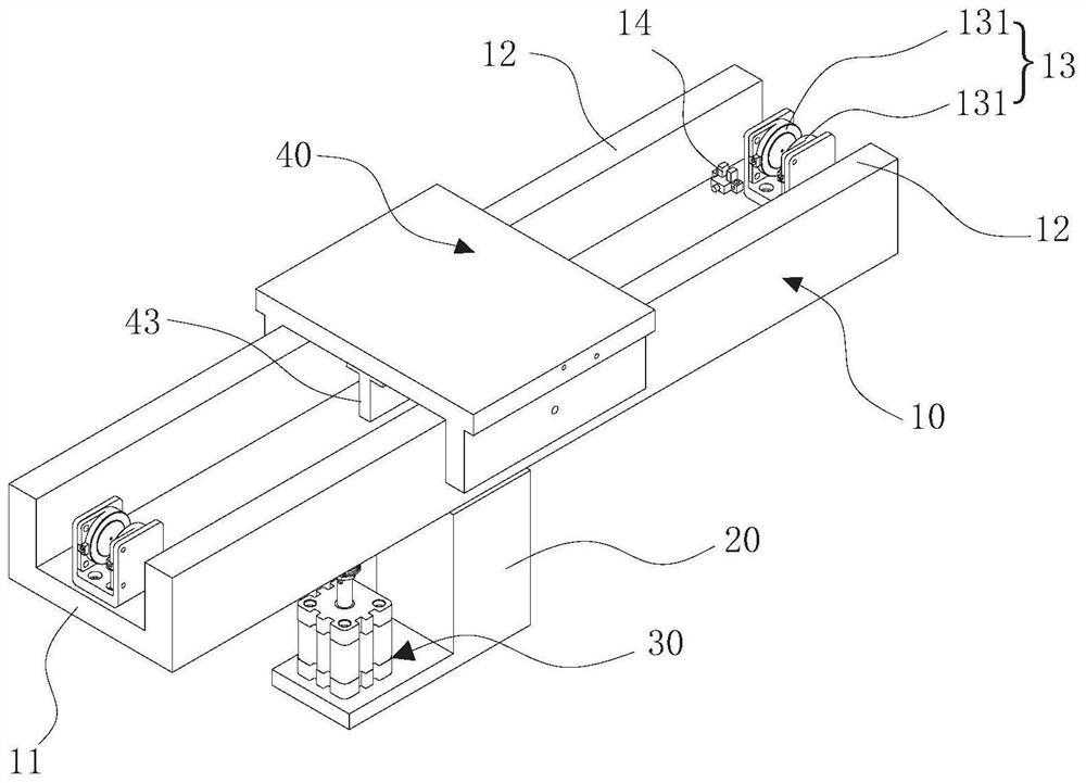
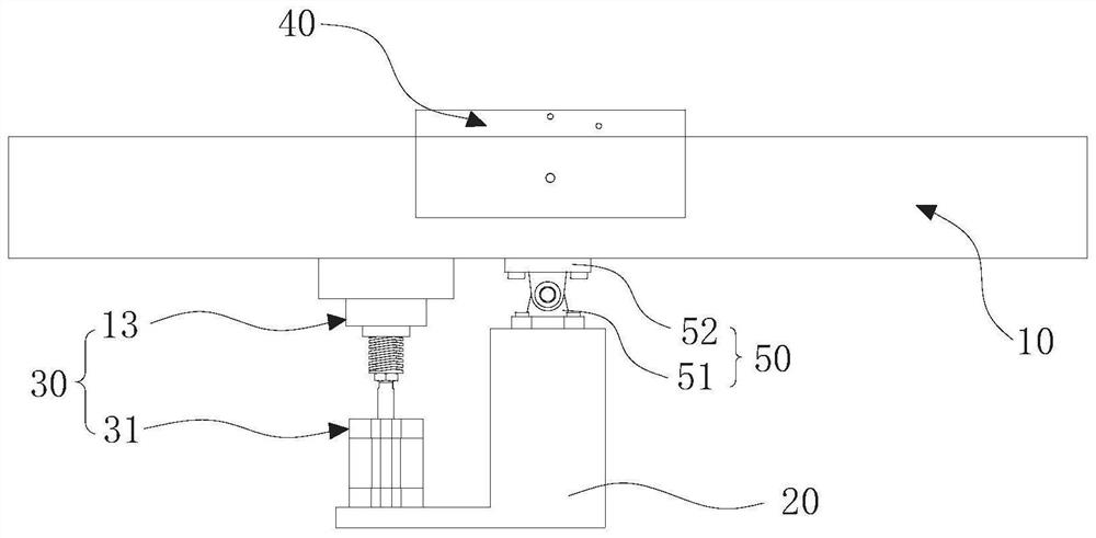
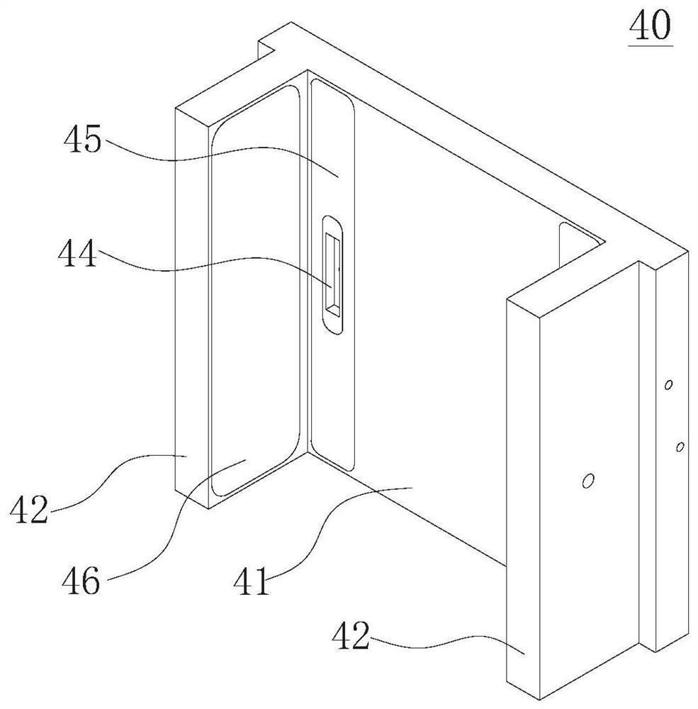
The embodiment of the invention discloses a conveying device, and relates to the technical field of conveying equipment. The conveying device comprises a conveying assembly, a base and a power assembly; the conveying assembly is hinged to the base and used for conveying workpieces; the power assembly is arranged on one side of the base and fixedly connected with the conveying assembly, and the power assembly is used for driving the conveying assembly to enable the conveying assembly to incline so as to convey the workpieces; the power assembly comprises a power unit and a correction unit, the correction unit is arranged between the power unit and the conveying assembly, the power unit is used for driving the conveying assembly to enable the conveying assembly to incline, and the correction unit is used for error self-adaptive correction of the conveying device. The conveying device is simple in structure, easy to mount and dismount and low in cost; and meanwhile, through self-adaptive correction of the conveying device, errors in the workpiece conveying process are reduced, and precise conveying is achieved.

Description

technical field [0001] The invention relates to the technical field of transmission equipment, in particular to a transfer device. Background technique [0002] The precision platform is a complex dynamic system, and its hardware composition, control system, guide rail support form and driving mode will all affect its comprehensive performance. At present, the air-floating positioning platform has the advantages of high speed, fast response, small friction, high precision, etc., and it is easy to achieve long strokes. It has become the main direction of the development of precision positioning platforms. Therefore, it is of great significance to study the characteristics of the air bearing guide rail of the two-dimensional linear drive air bearing platform, the precise control of the linear motor and the compensation of the linear positioning error to improve the positioning accuracy and stability of the system and realize high-speed precision feed positioning. [0003] At ...

Claims


Application Information

Patent Timeline
IPC IPC(8): B65G47/74B65G43/00
CPCB65G47/74B65G43/00
Inventor 夏笔樊景风陈根余陈焱高云峰
Owner HANS LASER TECH IND GRP CO LTD
Learn More