
Engine cooling system and vehicle

An engine cooling and coolant technology, which is applied in the direction of engine cooling, engine components, and engine lubrication, can solve the problems of low engine economy and low accuracy of coolant flow control, and achieves increased heat dissipation and reduced fuel consumption. , the effect of improving the economy

Inactive Publication Date: 2021-06-22
FAW JIEFANG AUTOMOTIVE CO
View PDF4 Cites 0 Cited by
  • Summary
  • Abstract
  • Description
  • Claims
  • Application Information

AI Technical Summary

Problems solved by technology

[0004] Based on this, it is necessary to provide an engine cooling system and a vehicle that can improve engine economy for the problem that the coolant flow control accuracy of the existing engine cooling system is not high, resulting in low engine economy.

Method used


Image

  • Engine cooling system and vehicle

Examples


Embodiment Construction

[0034] In order to make the above-mentioned purpose, features and advantages of the present application more obvious and understandable, the specific implementation manners of the present application will be described in detail below in conjunction with the accompanying drawings. In the following description, numerous specific details are set forth in order to provide a thorough understanding of the application. However, the present application can be implemented in many other ways different from those described here, and those skilled in the art can make similar improvements without departing from the connotation of the present application, so the present application is not limited by the specific embodiments disclosed below.

[0035] In the description of the present application, it should be understood that the terms "center", "longitudinal", "transverse", "length", "width", "thickness", "upper", "lower", "front", " Back", "Left", "Right", "Vertical", "Horizontal", "Top", "...


PUM


Abstract

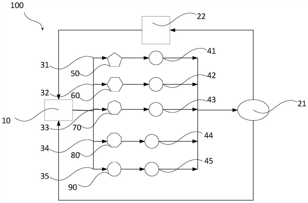
The invention relates to an engine cooling system which comprises a cooling liquid pump and a branch set. The input end and the output end of the branch set are connected with the cooling liquid pump, and the branch set comprises a first branch and a second branch which are arranged in parallel. The first branch is provided with an engine water jacket, a first proportional valve and a first temperature detector, and the engine water jacket is arranged at the upstream position of the first proportional valve and the first temperature detector in the flowing direction of cooling liquid. The second branch is provided with an EGR cooler, a second proportional valve and a second temperature detector, and the EGR cooler is arranged at the upstream position of the second proportional valve and the second temperature detector in the flowing direction of cooling liquid. The first proportional valve adjusts the flow of the cooling liquid in the first branch according to the detected temperature. The second proportional valve adjusts the flow of the cooling liquid in the second branch according to the detected temperature. According to the engine cooling system, the flow of the cooling liquid in each branch can be increased, and the heat dissipating capacity of the system is increased. Meanwhile, the oil consumption can be reduced, and the economical efficiency of an engine is improved.

Description

technical field [0001] The present application relates to the technical field of automobile engines, in particular to an engine cooling system and a vehicle. Background technique [0002] The role of the engine cooling system is to ensure that the engine works at the most suitable temperature under all working conditions. Whether the cooling system is properly matched will directly affect the service life and fuel economy of the engine. [0003] However, each component in the existing engine cooling system distributes the flow depending on its own flow resistance characteristics. This distribution method has low flow control accuracy and excessive coolant flow, which is not conducive to the economy of the engine. Contents of the invention [0004] Based on this, it is necessary to provide an engine cooling system and a vehicle capable of improving engine economy to solve the problem that the coolant flow control accuracy of the existing engine cooling system is not high, r...

Claims


Application Information

Patent Timeline
IPC IPC(8): F01P3/20F01P7/16F02M26/28F01M5/00F01M5/02F01N3/20F04B39/06
CPCF01M5/002F01M5/021F01N3/2046F01P3/20F01P7/16F01P7/165F01P2007/146F04B39/06F02M26/28Y02A50/20
Inventor 张青巧吕小井席凯汤旭财龚宝魏文李晶晶阮志强沈华中韩旭东
Owner FAW JIEFANG AUTOMOTIVE CO
Learn More