
Hydroelectric power generation device

A technology for hydroelectric power generation devices and generators, which is applied in the directions of hydropower generation, electromechanical devices, electrical components, etc., can solve the problems of complex structure and high environmental requirements, and achieve the effect of simple structure

Inactive Publication Date: 2021-06-22
麦麦提阿布杜瓦依提
View PDF0 Cites 1 Cited by
  • Summary
  • Abstract
  • Description
  • Claims
  • Application Information

AI Technical Summary

Problems solved by technology

[0002] The basic principle of hydroelectric power generation is to use the water level drop to cooperate with the hydroelectric generator to generate electricity, that is, to use the potential energy of the water to convert the mechanical energy of the water wheel, and then use the mechanical energy to drive the generator to obtain electricity. Most of the existing hydroelectric power generation devices Water turbines are used to generate electricity. Hydroelectric turbines have high environmental requirements and complex structures. In the agricultural field, farmland needs to be irrigated frequently. After the water flows out of the pipeline, it has a certain potential energy and kinetic energy. How to collect and store the potential energy and kinetic energy of water? Improving energy efficiency is an urgent problem to be solved.

Method used

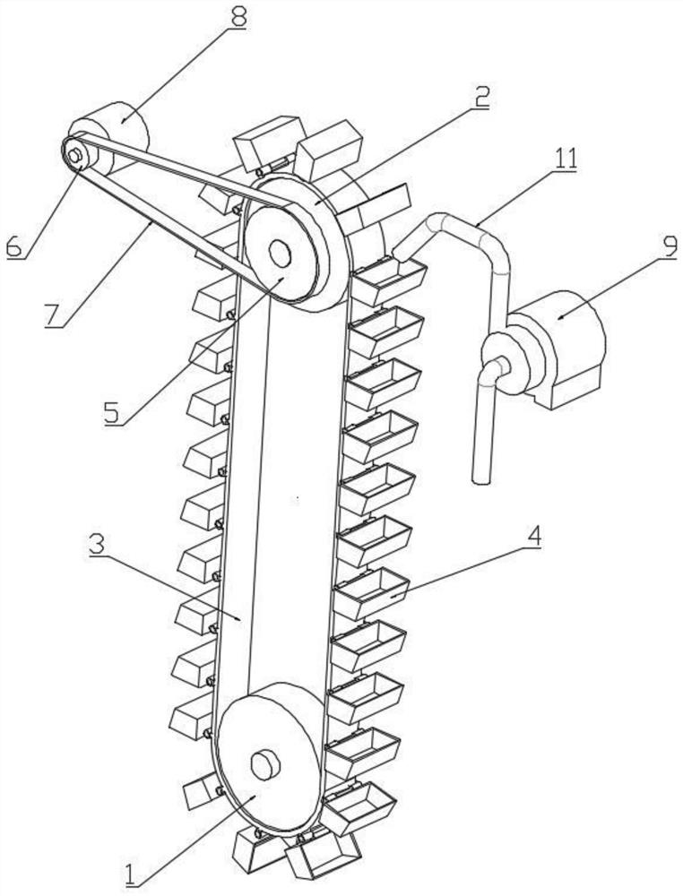

Image

  • Hydroelectric power generation device
  • Hydroelectric power generation device
  • Hydroelectric power generation device

Examples


Embodiment Construction

[0015] A hydroelectric power generation device of the present invention will be further described in detail below in conjunction with the accompanying drawings.

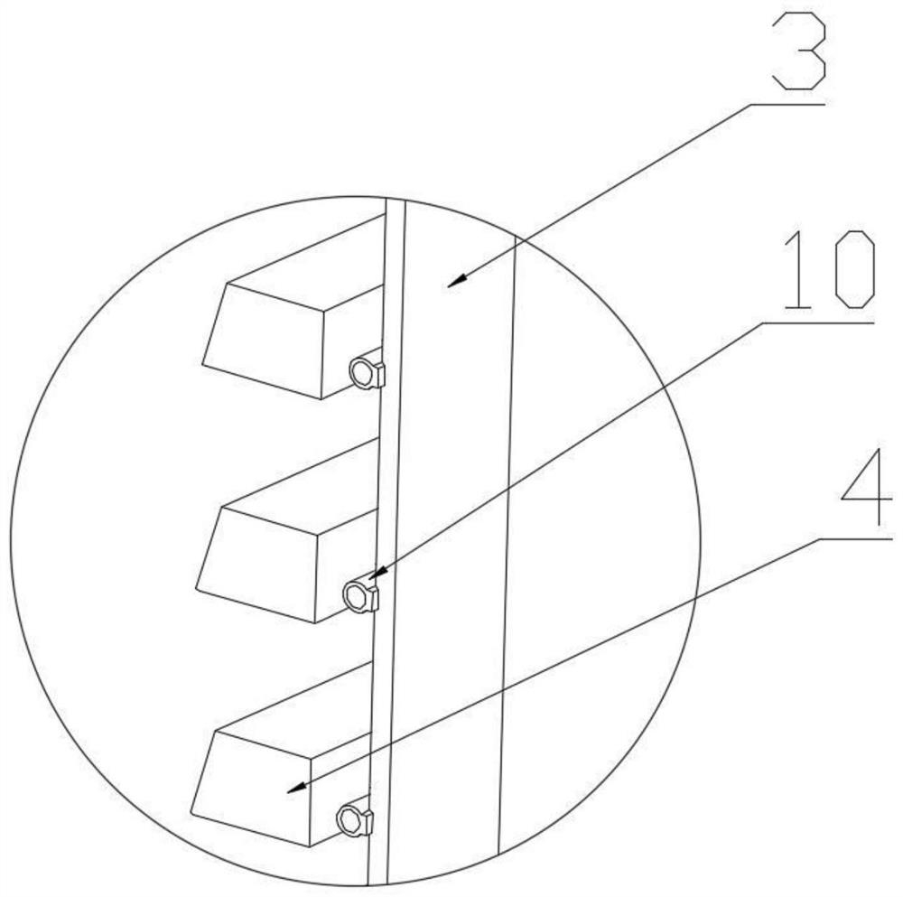
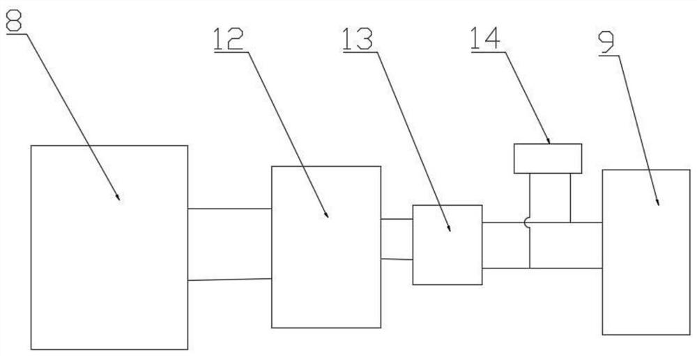
[0016] combined with figure 1 - attached image 3 , a hydroelectric power generation device comprising a generator 8, a water pump 9, a first pulley 1 and a second pulley 2 arranged above the first pulley 1, the first pulley 1 and the second pulley 2 are connected by a conveyor belt 3, so The conveying belt 3 is uniformly provided with a hinged shaft 4 along the circumferential direction, the conveying belt 3 is connected with the water tank 4 through a hinged shaft 10, and the central axis of the second belt pulley 2 is provided with a drive pulley 5, and the drive pulley 5 passes through the drive belt 7 is connected with the driven wheel 6 that is arranged on the shaft end of the generator 1.

[0017] As a preferred implementation of this embodiment, the output end of the generator 9 is connected to the battery ...


PUM


Abstract

The invention relates to the field of energy, and specifically relates to a hydroelectric power generation device. The hydroelectric power generation device comprises a power generator, a water pump, a first belt pulley and a second belt pulley arranged above the first belt pulley, wherein the first belt pulley and the second belt pulley are connected through a conveying belt, and hinge shafts are evenly arranged on the conveying belt in the circumferential direction; the conveying belt is connected with a water tank through the hinge shafts, a driving wheel is installed and arranged on a center shaft of the second belt wheel and connected with a driven wheel arranged at a shaft end of the power generator through a transmission belt, an output end of the power generator is connected with a storage battery through a conductive wire, and an output end of the storage battery is connected with an inverter; and a wire outlet of the inverter is connected with an external power supply in parallel and then is connected with a wire inlet of the water pump.

Description

technical field [0001] The invention relates to the field of energy, in particular to a hydroelectric power generation device. Background technique [0002] The basic principle of hydroelectric power generation is to use the water level drop to cooperate with the hydroelectric generator to generate electricity, that is, to use the potential energy of the water to convert the mechanical energy of the water wheel, and then use the mechanical energy to drive the generator to obtain electricity. Most of the existing hydroelectric power generation devices Water turbines are used to generate electricity. Hydroelectric turbines have high environmental requirements and complex structures. In the agricultural field, farmland needs to be irrigated frequently. After the water flows out of the pipeline, it has a certain potential energy and kinetic energy. How to collect and store the potential energy and kinetic energy of water? Improving energy efficiency is an urgent problem to be so...

Claims


Application Information

Patent Timeline
IPC IPC(8): F03B13/00F03B9/00H02K7/18
CPCF03B9/005F03B13/00F05B2220/706H02K7/1807Y02E10/20
Inventor 麦麦提·阿布杜瓦依提
Owner 麦麦提阿布杜瓦依提
Learn More