Straight-through type vacuum glass solar heat collecting tube

A solar collector tube and vacuum glass technology, which is applied to solar collectors, solar thermal energy, solar thermal power generation, etc., can solve the problems of increasing intelligence, inconsistent positioning of inner and outer tubes, and inconsistent positioning, to avoid Difficult to fix, ensure stability, and achieve uniform positioning

Active Publication Date: 2021-06-22
SHANDONG LANDBRIDGE PETROCHEMICAL CO LTD
View PDF6 Cites 0 Cited by
  • Summary
  • Abstract
  • Description
  • Claims
  • Application Information

AI Technical Summary

Problems solved by technology

[0003] Solar water heaters mainly use heat collecting tubes to collect heat. The solar heat collecting tubes are generally divided into inner tubes and outer tubes. The nozzles of the inner tubes and outer tubes are sealed together, and then the solar tubes are vacuumed to create a vacuum In order to facilitate the sealing of solar collector tubes, thermal melting is generally used for heat sealing. However, when the existing devices are heat sealed, there may be problems that the positioning of the inner tube and the outer tube is not uniform and the preheating time cannot be controlled. , thus negatively impacting the production of solar
[0004] Aiming at the deficiencies of the prior art, the present invention provides a straight-through vacuum glass solar collector tube, which has the advantages of uniform positioning and isochronous preheating, and solves the problem of non-uniform positioning and preheating time during the production and processing of existing solar energy. The uncontrollable problem ensures that when the device is used for operation, the inner tube and the outer tube can be automatically positioned, and at the same time, automatic preheating is performed after positioning, and the preheating time is kept consistent, so the success rate of heating tube production is improved. , to avoid the position inclination affecting the heat sealing effect of the water heater, and increase the intelligence of the device when it is used

Method used


Image

  • Straight-through type vacuum glass solar heat collecting tube
  • Straight-through type vacuum glass solar heat collecting tube
  • Straight-through type vacuum glass solar heat collecting tube

Examples


Embodiment 1

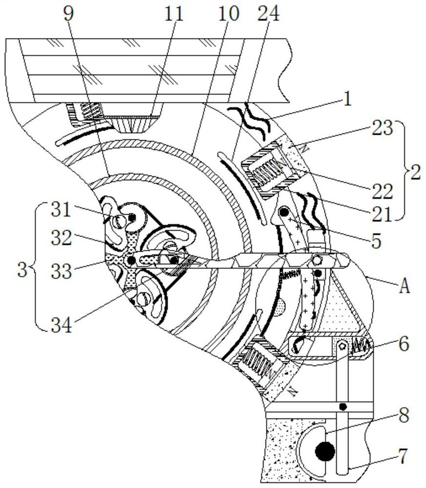
[0026] see figure 1 , a straight-through vacuum glass solar collector tube, comprising an outer tube limiting mechanism 2, the outer tube limiting mechanism 2 includes a fixed frame 21, the inside of the fixed frame 21 is provided with a cavity, and the size of the cavity is the same as that of the electromagnet 22 The size of the electromagnet 22 is adapted to each other, and the magnetism generated by the electromagnet 22 is the same as the magnetic pole of the fixed magnet 23, so that the electromagnet 22 can move along the cavity provided inside the fixed frame 21 to ensure the stability when moving. The movement of the electromagnet 22 drives the outer brake plate 24 to move synchronously. The interior of the fixed frame 21 is clamped with the electromagnet 22. The bottom end of the fixed frame 21 is welded with a fixed magnet 23. The end of the electromagnet 22 away from the fixed magnet 23 is engaged There are outer brake plates 24, and the number of outer brake plates ...

Embodiment 2

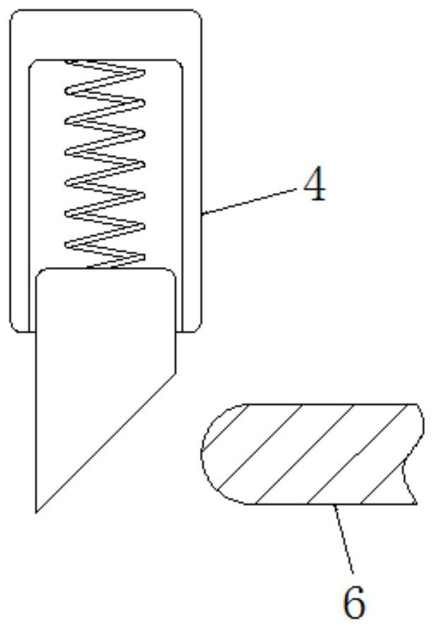
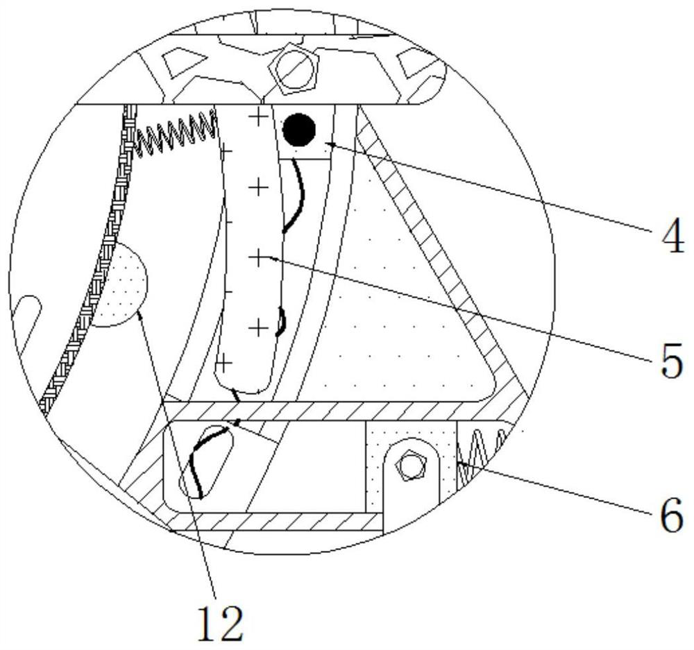
[0029] see figure 1 , a straight-through vacuum glass solar collector tube, including an inner tube limit mechanism 3, an inner brake plate 31 is rotatably connected to the inner end of the outer brake plate 24, and an inner brake plate 32 is rotatably connected to the surface of the disc 31, and the inner brake plate 32 is used to rotate the inner end of the outer brake plate 24. The swing of the brake plate 32 simultaneously limits the position of the inner tube 9 to ensure the stability of the inner tube 9. The back of the disc 31 is clamped with a connecting plate 33, and the movement of the connecting plate 33 drives the disc 31 to rotate synchronously. , the surface of the connecting plate 33 is rotatably connected with a handle 34, the movement of the handle 34 drives the connecting plate 33 to move synchronously, the back of the outer tube limit mechanism 2 is fixedly connected to the support seat 1, and the support seat 1 is internally clamped with a moving block 4, T...

Embodiment 3

[0032] see Figure 1-3, a straight-through vacuum glass solar collector tube, comprising an outer tube limiting mechanism 2, the outer tube limiting mechanism 2 includes a fixed frame 21, the inside of the fixed frame 21 is provided with a cavity, and the size of the cavity is the same as that of the electromagnet 22 The size of the electromagnet 22 is adapted to each other, and the magnetism generated by the electromagnet 22 is the same as the magnetic pole of the fixed magnet 23, so that the electromagnet 22 can move along the cavity provided inside the fixed frame 21 to ensure the stability when moving. The movement of the electromagnet 22 drives the outer brake plate 24 to move synchronously. The interior of the fixed frame 21 is clamped with the electromagnet 22. The bottom end of the fixed frame 21 is welded with a fixed magnet 23. The end of the electromagnet 22 away from the fixed magnet 23 is engaged There are outer brake plates 24, and the number of outer brake plate...


PUM


Abstract

The invention relates to the technical field of water heaters, and discloses a straight-through type vacuum glass solar heat collecting tube which comprises an outer tube limiting mechanism. The outer tube limiting mechanism comprises a fixing frame; when a handle swings, a disc is driven to rotate, so that an inner-layer tube is automatically clamped and limited by linkage of an inner brake plate, the stability of the inner-layer tube during heat sealing is guaranteed, and the situation that the inner-layer tube is difficult to fix is avoided; a fixed magnet drives an outer brake plate to approach to an outer-layer tube after being electrified, so that the outer-layer tube is automatically limited while the inner-layer tube is limited, the inner-layer tube and the outer-layer tube are ensured to be concentrically arranged, and machining is more convenient; and through cooperative use of a moving block, a touch plate and a sliding block, when the handle moves, the moving block is driven to synchronously move and finally clamped with a groove, so that a heating gun automatically heats to seal the tube, a special-shaped disc is triggered to rotate, clamping is finally lost, and the heating gun is ensured to conduct heating isochronously to conduct heat sealing.

Description

technical field [0001] The invention relates to the technical field of water heaters, in particular to a straight-through vacuum glass solar heat collection tube. Background technique [0002] With the rapid development of modern society and economy, human beings demand more and more energy. Solar energy is an inexhaustible clean energy with a huge amount of resources. conversion device. [0003] Solar water heaters mainly use heat collecting tubes to collect heat. The solar heat collecting tubes are generally divided into inner tubes and outer tubes. The nozzles of the inner tubes and outer tubes are sealed together, and then the solar tubes are vacuumed to create a vacuum In order to facilitate the sealing of solar collector tubes, thermal melting is generally used for heat sealing. However, when the existing devices are heat sealed, there may be problems that the positioning of the inner tube and the outer tube is not uniform and the preheating time cannot be controlled....

Claims


Application Information

Patent Timeline
Patent Type & Authority Applications(China)
IPC IPC(8): F24S10/40F24S25/60F24S80/58
CPCF24S10/40F24S25/60F24S80/58Y02E10/44Y02E10/47
Inventor 吴伟荣
Owner SHANDONG LANDBRIDGE PETROCHEMICAL CO LTD
Why Eureka
Try Eureka