A threshing drum applied to edible bean threshing equipment

A threshing drum and equipment technology, applied in threshing equipment, application, agriculture, etc., can solve the problems that it is difficult to adapt to multi-variety bean pods, high bean damage rate, and difficult to adjust the gap between the nail teeth and the inner wall of the sieve plate threshing chamber, so as to reduce crushing rate, improve the effect of threshing, and the effect of uniform pressure

Active Publication Date: 2022-04-12
NANJING AGRI MECHANIZATION INST MIN OF AGRI
View PDF5 Cites 0 Cited by
  • Summary
  • Abstract
  • Description
  • Claims
  • Application Information

AI Technical Summary

Problems solved by technology

The defects of the prior art threshing drum are: 1. The nail teeth on the surface of the drum are a cylindrical object, and the rubbing of the bean pods by the nail teeth is a rigid extrusion, resulting in a relatively high rate of damage to the beans after threshing; It is difficult to adjust the gap between the sieve plate or the inner wall of the threshing bin, which makes it difficult for the threshing equipment to adapt to the pods of various varieties and sizes

Method used


Image

  • A threshing drum applied to edible bean threshing equipment
  • A threshing drum applied to edible bean threshing equipment
  • A threshing drum applied to edible bean threshing equipment

Examples


Embodiment 1

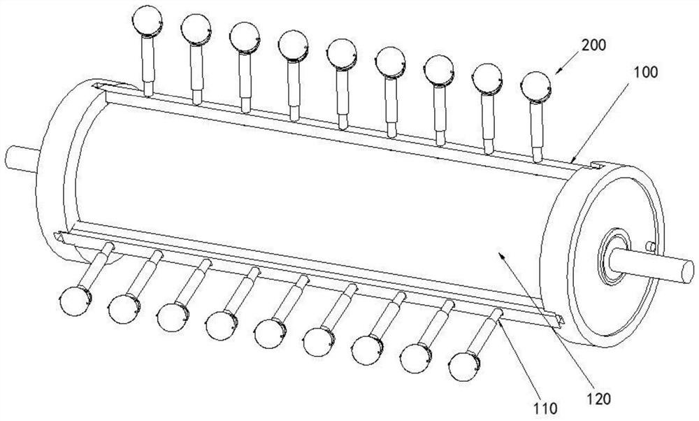
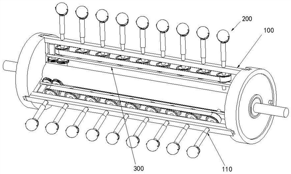
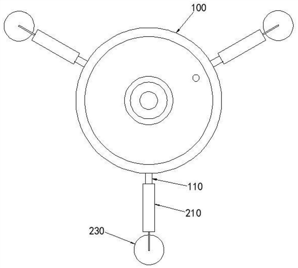
[0027] Such as Figure 1 to Figure 4 As shown, the threshing drum applied to edible bean threshing equipment in this embodiment includes a drum 100, a spike assembly 200 and an adjustment assembly 300;

[0028] Three rows of mounting rods 110 are arranged on the surface of the drum 100;

[0029] The nail-tooth assembly 200 includes a fixed rod 210, a rotating shaft 220 and a ball 230. The ball 230 is mounted on one end of the fixed rod 210 through the rotating shaft 220. The ball 230 can rotate around the rotating shaft 220. The rotating shaft 220 is parallel to the central axis of the drum 100. The fixed rod 210 Connect with the mounting rod 110;

[0030] The adjustment assembly 300 includes a mounting plate 310, a motor 320, a second gear set 330, a synchronous pulley 340 and a belt 350, and the mounting rod 110 is screwed to the drum 100, and all the mounting rods 110 are equipped with a synchronous pulley 340, the same row The synchronous pulley 340 on the mounting bar 1...

Embodiment 2

[0034] Such as Figure 5 to Figure 9 As shown, the difference between this embodiment and Embodiment 1 lies in the nail-tooth assembly 200. The nail-tooth assembly 200 in this embodiment includes a fixed rod 210, a housing 240, a first gear set 250, a first cylinder 260, a second Two cylinders 270, the first rotating shaft 280 and the second rotating shaft 290, the housing 240 is connected with the fixed rod 210, the two ends of the first cylinder 260 are connected to the housing 240 through the first rotating shaft 280, the two ends of the second cylinder 270 The housing 240 is connected through the second shaft 290, the first cylinder 260 is parallel to the second cylinder 270; the first gear set 250 is located in the housing 240, and the first gear set 250 is connected to the first shaft 280 and the second shaft 290, The surface of the first cylinder 260 is provided with transverse lines, and the distance between the outer edge of the first cylinder 260 and the center of th...


PUM


Abstract

The invention discloses a threshing drum applied to edible bean threshing equipment, which comprises a drum and a spike assembly; multiple rows of spike assemblies are arranged on the surface of the drum, and the spike assembly rotates synchronously with the drum; the spike assembly The assembly includes a fixed rod, a rotating shaft and a rolling body. The rolling body is installed on one end of the fixed rod through the rotating shaft. The rolling body can rotate around the rotating shaft. The rotating shaft is parallel to the central axis of the rotating drum, and the fixing rod is connected to the rotating drum. The threshing cylinder of the present invention uses a spike assembly with rolling elements to replace the traditional cylindrical spikes. The rolling elements themselves have a self-rotating function, which makes the pressure of the rolling elements on the pods more uniform and reduces the crushing rate of beans; at the same time, the rolling elements and The contact area of ​​the pods is larger, and the rolling body can also promote the pods to turn backwards, which is beneficial to improve the threshing effect of the pods.

Description

technical field [0001] The invention relates to the field of agricultural equipment, in particular to a threshing drum applied to edible bean threshing equipment. Background technique [0002] The edible bean threshing equipment in the prior art generally includes a threshing bin, a threshing drum and a sieve plate located in the threshing bin, and the threshing drum includes a drum and multiple rows of nail teeth on the surface of the drum; when performing threshing work, the drum is driven by a motor. Rotating, the teeth on the surface of the drum cooperate with the inner wall of the threshing chamber and the sieve plate to beat and knead the pods, so that the beans are separated from the pods. The defects of the prior art threshing drum are: 1. The nail teeth on the surface of the drum are a cylindrical object, and the rubbing of the bean pods by the nail teeth is a rigid extrusion, resulting in a relatively high breakage rate of the beans after threshing; The gap betwee...

Claims


Application Information

Patent Timeline
Patent Type & Authority Patents(China)
IPC IPC(8): A01F11/00A01F12/22
CPCA01F11/00A01F12/22
Inventor 占才学夏先飞杨光陈巧敏宋志禹梅松蒋清海丁文芹金月赵映韩余张健飞王文明
Owner NANJING AGRI MECHANIZATION INST MIN OF AGRI
Why Eureka
Try Eureka