
Transformer low-voltage side busbar flat bending and vertical bending integrated device

A technology for transformer low-voltage side and busbars, which is applied in the field of transformers, can solve the problems of high labor intensity, laborious labor, and increased procurement costs of construction units, and achieve the effect of avoiding scratches and reducing procurement costs

Active Publication Date: 2021-06-25
STATE GRID SHANDONG ELECTRIC POWER CO YUNCHENG POWER SUPPLY CO
View PDF7 Cites 0 Cited by
  • Summary
  • Abstract
  • Description
  • Claims
  • Application Information

AI Technical Summary

Problems solved by technology

Traditional busbar bending generally adopts manual bending or hydraulic bending machine bending. Manual bending is generally labor-intensive, especially for large-sized busbar bending, which is labor-intensive, and the bending angle varies depending on each application. Different forces will also cause differences in bending angles; the existing hydraulic bending machines are divided into flat bending machines and vertical bending machines according to their functions, and special bending machines are required for busbars with different bending requirements For example, when the busbar needs to be bent flat, use a flat bending machine for bending; when the busbar needs to be bent vertically, use a vertical bending machine for bending. The construction unit needs to purchase different bending machines. Increase the procurement cost of the construction unit

Method used


Image

  • Transformer low-voltage side busbar flat bending and vertical bending integrated device
  • Transformer low-voltage side busbar flat bending and vertical bending integrated device
  • Transformer low-voltage side busbar flat bending and vertical bending integrated device

Examples


Embodiment Construction

[0052] Attached below Figure 1-16 , clearly and completely describe the technical solutions in the embodiments of the present invention, obviously, the described embodiments are only some of the embodiments of the present invention, not all of them. Based on the embodiments of the present invention, all other embodiments obtained by persons of ordinary skill in the art without making creative efforts belong to the protection scope of the present invention.

[0053] In describing the present invention, it should be understood that the terms "longitudinal", "transverse", "upper", "lower", "front", "rear", "left", "right", "vertical", The orientations or positional relationships indicated by "horizontal", "top", "bottom", "inner", "outer", etc. are based on the orientations or positional relationships shown in the drawings, and are only for the convenience of describing the present invention, rather than indicating or It should not be construed as limiting the invention by impl...


PUM


Abstract

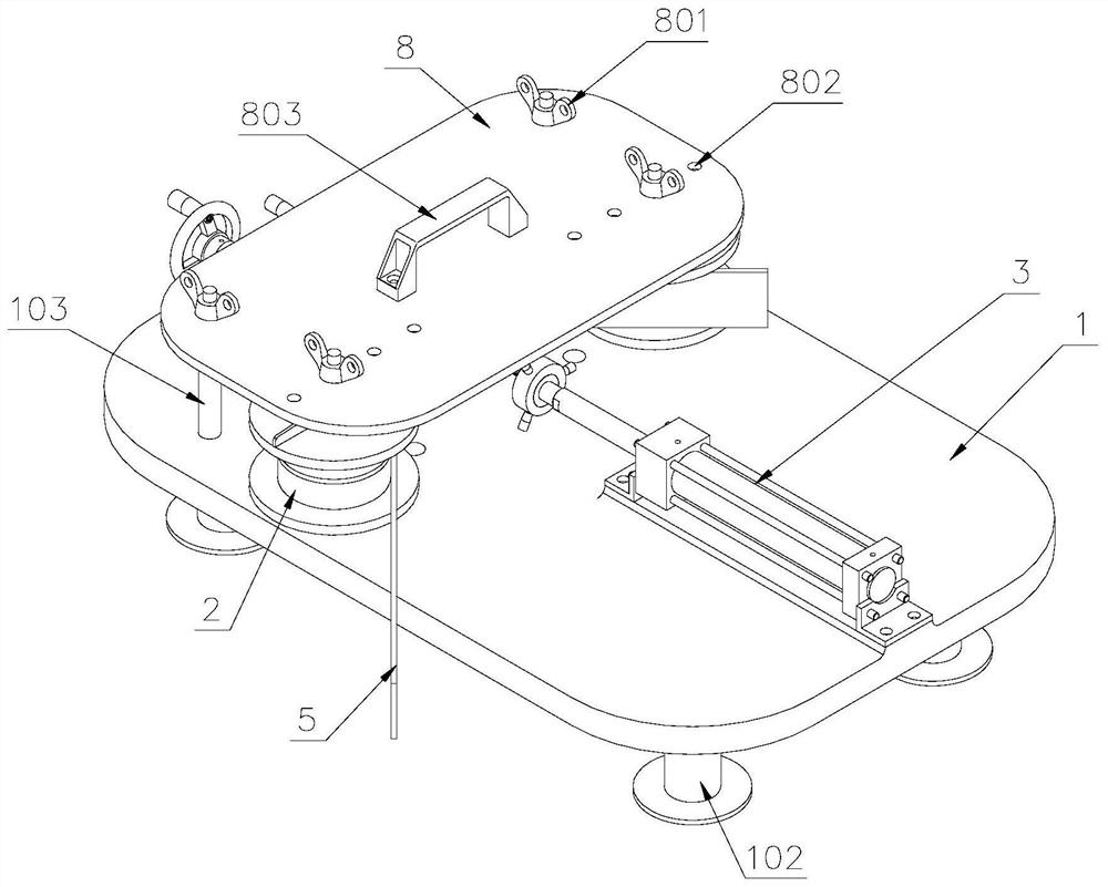
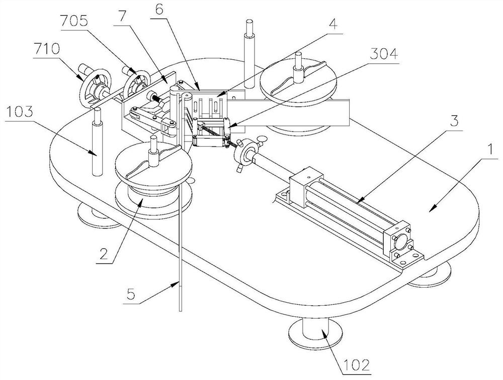
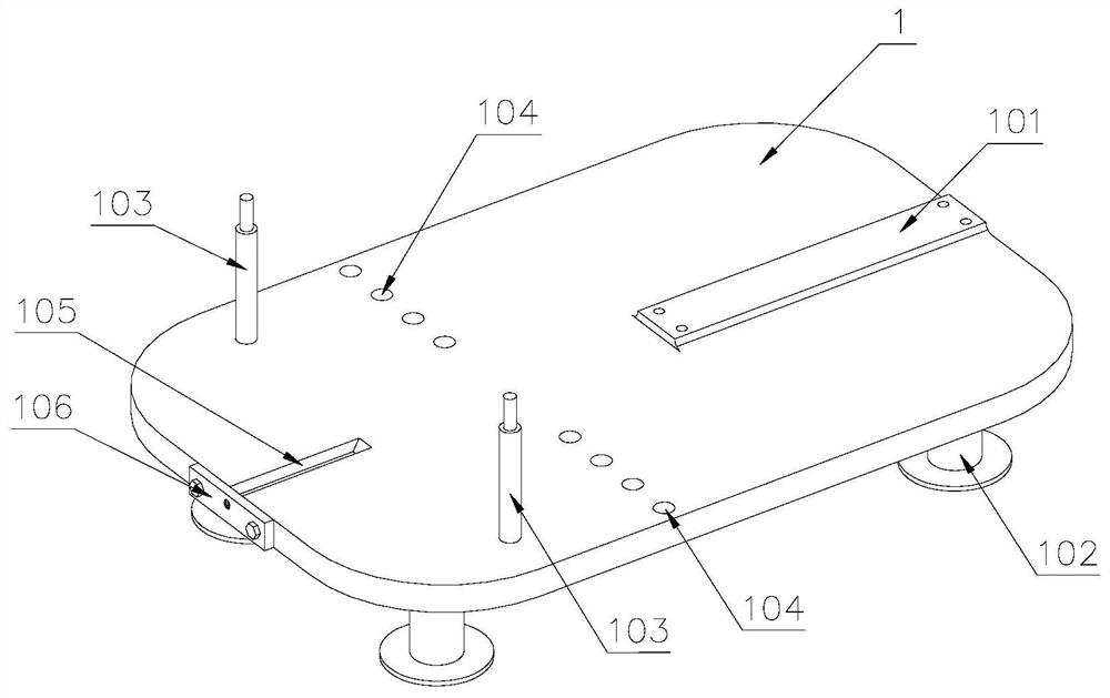
The invention discloses a transformer low-voltage side busbar flat bending and vertical bending integrated device. The transformer low-voltage side busbar flat bending and vertical bending integrated device comprises a base, rotating rollers, a hydraulic cylinder and a top die, the two sets of rotating rollers are symmetrically arranged on the two sides of the hydraulic cylinder, a first clamping groove is formed in the middle of each rotating roller, during flat bending, a busbar is placed on the same side of the rotating rollers, and during vertical bending, the busbar is placed in the first clamping grooves of the rotating rollers on the two sides; one end of a piston rod of the hydraulic cylinder is connected with the top die which is of a V-shaped structure; and L-shaped clamping plates which are symmetrical up and down are arranged in the middles of the two sides of the top die, a second clamping groove is formed between the two L-shaped clamping plates, and the busbar is placed between the first clamping grooves and the second clamping groove during vertical bending. According to the transformer low-voltage side busbar flat bending and vertical bending integrated device, the hydraulic cylinder is arranged on the base, the rotating rollers are arranged on the two sides of the hydraulic cylinder, the busbar is placed on one sides of the rotating rollers when the busbar is horizontally bent, the busbar is placed in the first clamping grooves of the rotating rollers on the two sides when the busbar is vertically bent, the hydraulic cylinder is used for driving the top die to bend the busbar, horizontal bending and vertical bending of the busbar are integrated, and the purchase cost of a construction unit is reduced.

Description

technical field [0001] The invention belongs to the technical field of transformers, and in particular relates to a flat-bending and vertical-bending integrated device for a low-voltage side busbar of a transformer. Background technique [0002] Copper or aluminum bars, also known as bus bars, are made of copper or aluminum and have a rectangular or chamfered (rounded) rectangular cross-section. In the power supply system, it is used as the connection between the master switch in the electric cabinet and the switches in each branch circuit. The surface of the copper bar or aluminum bar is insulated, and its main function is to be used as a wire. [0003] In modern power grid construction, the installation of transformers is often involved. For example, when installing power substations, power distribution devices, and electrical engineering, copper bars or aluminum bars are required to connect electrical equipment. Large current-carrying connections require large copper ba...

Claims


Application Information

Patent Timeline
Patent Type & Authority Applications(China)
IPC IPC(8): B21D7/06B21D7/04B21D7/16
CPCB21D7/06B21D7/04B21D7/16
Inventor 冯昌军范洪群徐晨曦宋奇任少坤张建利李守鹏谢明秋许兆涛王永立郭朔桑盛强张爱明李颖王志鹏
Owner STATE GRID SHANDONG ELECTRIC POWER CO YUNCHENG POWER SUPPLY CO
Learn More