Saw blade edging equipment for metal cutter machining

A technology for cutting tools and saw blades, which is applied in the field of saw blade cutting equipment for metal cutting tool processing, can solve the problem of low efficiency of manual grinding, and achieve the effect of saving manpower and preventing rust.

Active Publication Date: 2021-06-25
湖北鄂嘉科技有限公司
View PDF5 Cites 0 Cited by
  • Summary
  • Abstract
  • Description
  • Claims
  • Application Information

AI Technical Summary

Problems solved by technology

[0004] In order to overcome the disadvantages that although the saw blade is not very sharp before being polished, it is dangerous to a certain extent, and the efficiency of manual polishing is not high, the technical problem of the present invention is: to provide a fast saw blade that does not need to be manually polished. Saw blade sharpening equipment for metal tool processing

Method used


Image

  • Saw blade edging equipment for metal cutter machining
  • Saw blade edging equipment for metal cutter machining
  • Saw blade edging equipment for metal cutter machining

Examples


Embodiment 1

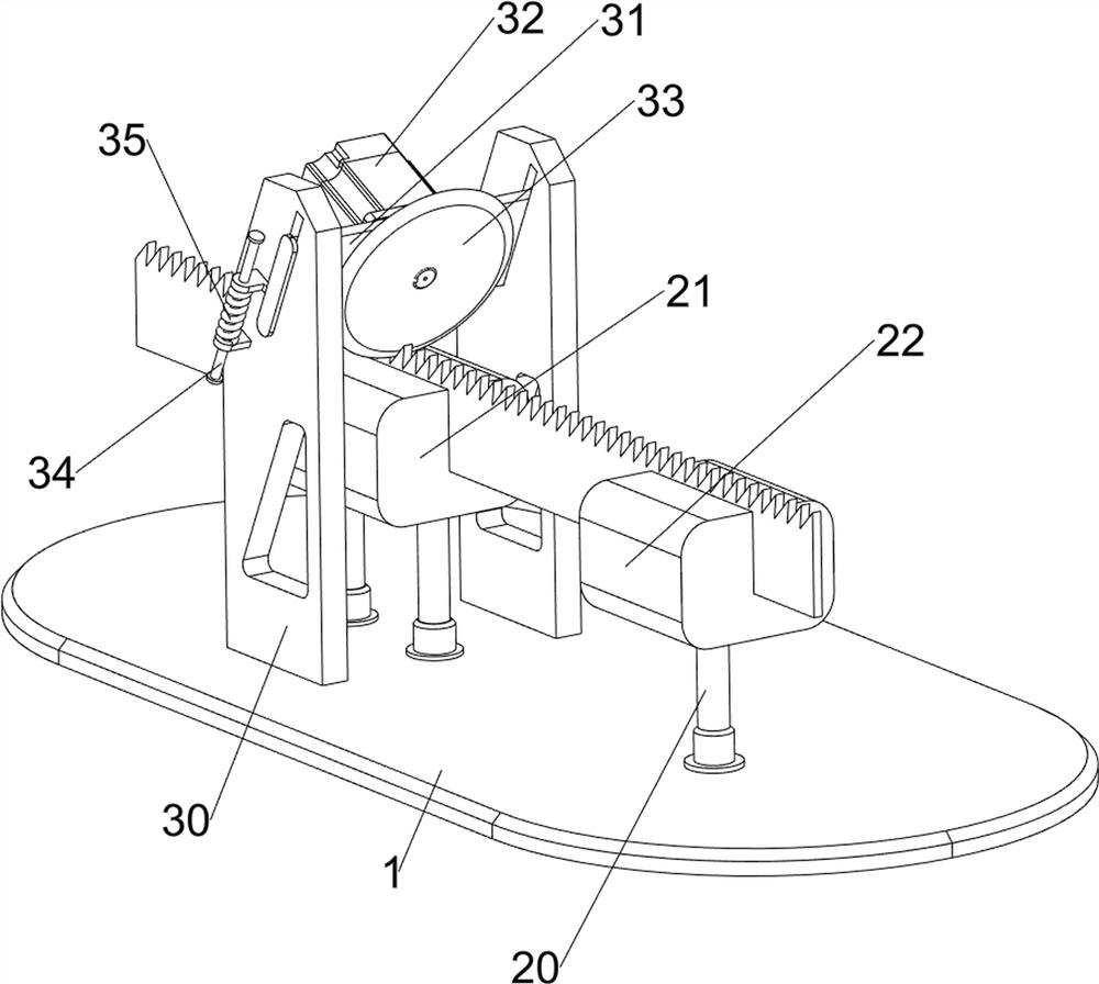
[0059] A saw blade sharpening device for metal tool processing, such as figure 1 As shown, it includes a bottom plate 1 , a fixing mechanism 2 and a cutting mechanism 3 , the top of the bottom plate 1 is provided with a fixing mechanism 2 , and the left side of the top of the bottom plate 1 is provided with a cutting mechanism 3 .

[0060] Such as figure 2 As shown, the sharpening mechanism 3 includes a first mounting plate 30, a slide plate 31, a first motor 32, a grinding wheel 33, a limit rod 34 and a first spring member 35, and the left side of the top of the base plate 1 is symmetrically provided with the first mounting plate 30, a slide plate 31 is slidably connected between the first mounting plates 30, a first motor 32 is provided on the slide plate 31, a grinding wheel 33 is connected to the output shaft of the first motor 32, and limit rods are slidingly provided on the outside of the first mounting plate 30 34 , the sliding plate 31 is connected to the limit rod 3...

Embodiment 2

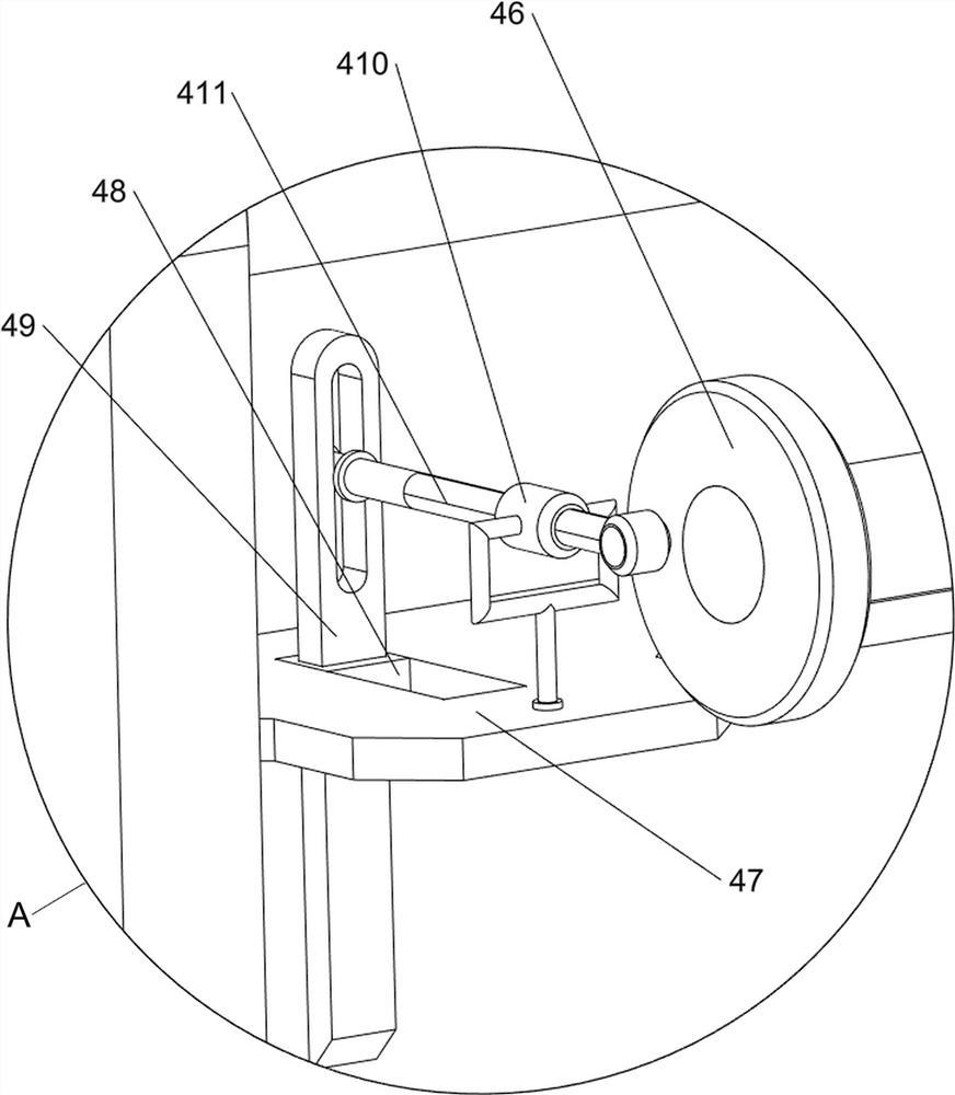
[0064]On the basis of Example 1, such as image 3 and Figure 4 As shown, a propulsion mechanism 4 is also included, and the propulsion mechanism 4 includes a second mounting plate 40, a second motor 41, a rotating shaft 42, a pulley set 43, a turret 44, a cam 45, a runner 46, a third mounting plate 47, Slider 48, first push rod 49, fixed frame 410 and second push rod 411, base plate 1 top right rear side are provided with second motor 41, base plate 1 top right side is provided with second mounting plate 40 symmetrically front and rear, rear side The second mounting plate 40 is rotatably provided with a rotating shaft 42, and a pulley group 43 is connected between the rotating shaft 42 and the output shaft of the second motor 41, and a turret 44 is rotationally connected between the second mounting plate 40, and the rear side of the rotating shaft 42 is arranged There is a cam 45, the turret 44 cooperates with the cam 45 and the limit rod 34, the front side of the rotating s...


PUM


Abstract

The invention relates to edging equipment, in particular to saw blade edging equipment for metal cutter machining. The invention has the technical problem of providing saw blade edging equipment for metal cutter machining, which can rapidly carry out edging on a saw blade without manually carrying out the grinding work. The saw blade edging equipment for metal cutter machining comprises a bottom plate and an edging mechanism, wherein a fixing mechanism is arranged at the top of the bottom plate; and the edging mechanism is arranged on one side of the top of the bottom plate. A to-be-ground saw blade can be placed through the arranged fixing mechanism; saw teeth of the saw blade can be ground through the arranged edging mechanism; and by an arranging pushing mechanism, the saw blade can be automatically pushed to move and a sliding plate is automatically enabled to move, so that manpower is further saved.

Description

technical field [0001] The invention relates to a sharpening device, in particular to a saw blade sharpening device for metal tool processing. Background technique [0002] The saw blade is a steel sheet with a toothed edge, and the toothed edge is the main part of the saw blade. During the use of the saw blade, in order to make the saw teeth of the saw blade smoother and sharper for better cutting, it is necessary to grind the saw teeth of the saw blade At present, it is generally used to attach abrasive paper to the surface of the saw teeth manually, and then move back and forth continuously to polish the saw teeth. However, although the saw blade is not very sharp before it is polished, it is also dangerous to a certain extent, and manual grinding is not efficient. [0003] Therefore need to design a kind of needn't manually carry out grinding work, the saw blade sharpening equipment of the metal tool processing of saw blade sharpening fast. Contents of the invention ...

Claims


Application Information

Patent Timeline
Patent Type & Authority Applications(China)
IPC IPC(8): B23D63/12
CPCB23D63/12
Inventor 杨智远
Owner 湖北鄂嘉科技有限公司
Why Eureka
Try Eureka