Cerebral hemorrhage puncture drainage tube

A drainage tube and drainage channel technology, which is applied to catheters, suction devices, hollow probes, etc., can solve problems such as blockage of drainage tubes, and achieve the effects of cost saving, improving drainage efficiency and simple operation.

Inactive Publication Date: 2022-02-08
THE FIRST AFFILIATED HOSPITAL OF HENAN UNIV OF SCI & TECH
View PDF0 Cites 0 Cited by
  • Summary
  • Abstract
  • Description
  • Claims
  • Application Information

AI Technical Summary

Problems solved by technology

[0004] In order to solve the problem of blockage of the puncture drainage tube for cerebral hemorrhage, the present invention provides a puncture drainage tube for cerebral hemorrhage. The bottom end of the drainage tube forms a drainage area, and the blood clot blocks the drainage hole in the drainage area. The blood clot in the area is physically broken, and the drug injection channel opened in the movable plug connects the drug distribution cavity and the drainage area, or blocks the drug injection channel to complete the precise delivery of hemolytic drugs

Method used


Image

  • Cerebral hemorrhage puncture drainage tube
  • Cerebral hemorrhage puncture drainage tube
  • Cerebral hemorrhage puncture drainage tube

Examples


Embodiment 1

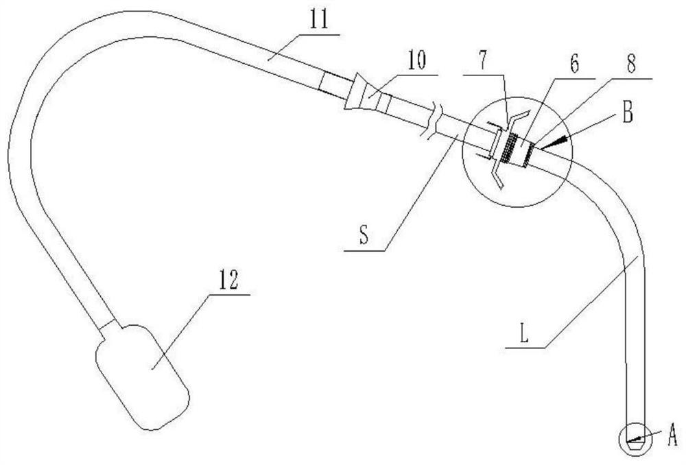
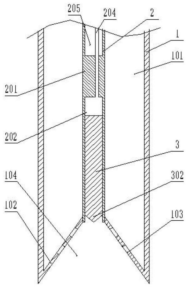
[0047] Such as figure 1 As shown, a puncture drainage tube for cerebral hemorrhage, the bottom of the drainage tube goes deep into the brain, and the top of the drainage tube is connected to an extension tube 11 through a connector 10, and the extension tube 11 is connected to a drainage bag 12. Such as Figure 2-3 As shown, the drainage tube includes an inner tube 2 and an outer tube 1 coaxially arranged, and a plurality of support bars are arranged between the outer wall of the inner tube 2 and the inner wall of the outer tube 1, and the support bars are evenly arranged along the circumferential direction of the inner wall of the outer tube 1 to ensure that the inner tube Tube 2 and outer tube 1 are coaxial, and the diameter of the support bars should be as thin as possible. A drainage channel 101 is formed between the inner tube 2 and the outer tube 1. The bottom end of the outer tube 1 exceeds the inner tube 2, and the drainage channel 101 is closed by an inclined annular...

Embodiment 2

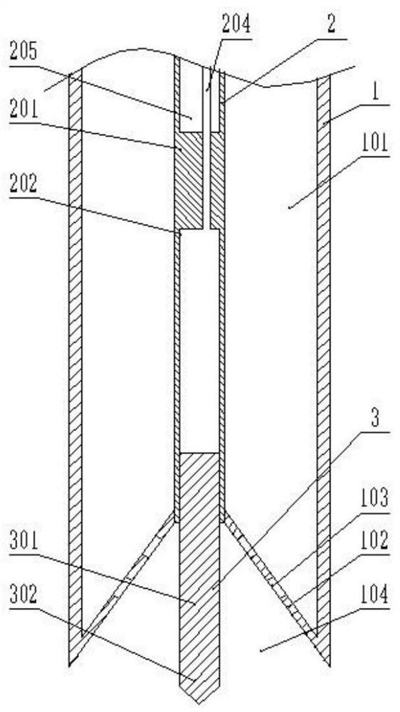
[0050] This embodiment is an improvement made on the basis of embodiment 1, its main structure is the same as that of embodiment 1, and the improvements are as follows: Figure 4-5 As shown, the bottom end of the outer tube 1 is fixedly connected with an arc-shaped sealing plate 105 that seals the drainage area 104. The surface of the arc-shaped sealing plate 105 forms an outwardly convex arc surface. A central hole for blood to enter the drainage area 104 . The setting of the arc-shaped sealing plate 105 forms a semi-closed drainage area 104 on the one hand, which can limit the position of the blood clot when breaking or injecting hemolytic drugs; To injure brain tissue and cranial nerves, the surface of the arc-shaped sealing plate 105 forms a circular arc surface, that is, a circular arc transition is performed on the spikes to prevent the spikes from piercing the brain tissue and cranial nerves.

Embodiment 3

[0052] This embodiment is an improvement made on the basis of embodiment 1 or embodiment 2, and its main structure is the same as that of embodiment 1 or embodiment 2. The point of improvement is that in embodiment 1, liquid volume is injected To control the displacement of the movable plunger 3, due to the small volume of the hydraulic expansion chamber 202, it is very difficult to control the volume of the injected liquid very precisely. Once the operation is improper, the movable plunger 3 will protrude from the drainage area 104, and even slide out of the hydraulic expansion chamber 202, and then stabbed the brain tissue and cranial nerves. Therefore, the bottom of the hydraulic expansion chamber 202 is fixedly connected with a block 203 around the inner wall. The block 203 can be a ring around the inner wall, and is fixedly connected with a limit block 304 around the top of the movable plug 3. In this embodiment, the movable plug 3 It consists of three parts, that is, the...


PUM


Abstract

A cerebral hemorrhage puncture drainage tube comprises an inner tube and an outer tube which are coaxially arranged, a drainage channel is formed between the inner tube and the outer tube, the bottom end of the outer tube exceeds the inner tube, the drainage channel is sealed by an inclined annular sealing plate between the outer tube and the inner tube, and the annular sealing plate forms a conical drainage region. A plurality of drainage holes communicated with the drainage region and the drainage channel are formed in the annular sealing plate; the bottom of the inner tube is provided with a solid section, the solid section divides the inner tube into a hydraulic telescopic cavity with an opening in the bottom end and a hollow tube section with an opening in the upper end, a movable plunger is arranged in the hydraulic telescopic cavity in a sliding mode, and the bottom end of the movable plunger is provided with a tip capable of breaking blood clots. Through injecting liquid into thehydraulic telescopic cavity, the bottom end of the movable plunger is pushed to extend out of the hydraulic telescopic cavity to physically crush the blood clots, or liquid in the hydraulic telescopic cavity is pumped out, so that the movable plunger retracts into the hydraulic telescopic cavity. Blood clots blocking the drainage holes can be treated conveniently, operation is easy, and cost is saved.

Description

technical field [0001] The invention relates to the field of medical devices, in particular to a puncture drainage tube for cerebral hemorrhage. Background technique [0002] In today's society, cerebral hemorrhage has become a common disease and frequently-occurring disease. Drug treatment is often used when the amount of bleeding is small. Surgery, small bone window craniotomy, hematoma removal, drilling hematoma aspiration, and ventricular puncture and drainage, among which ventricular puncture and drainage is to drain the cerebrospinal fluid, blood, etc. come out. [0003] Existing drainage tubes are small in volume, and the drainage holes are generally arranged on one to two small holes on the side wall of the end of the drainage tube. The drainage function of the drainage tube is weakened or even completely disappeared. At this time, it is necessary to clean up the blood clot or replace the drainage tube. Cleaning up the blood clot is time-consuming and laborious, wh...

Claims


Application Information

Patent Timeline
Patent Type & Authority Applications(China)
IPC IPC(8): A61M25/00A61M1/00
CPCA61M25/0026A61M25/007A61M25/0074A61M2025/0004A61M2025/0039A61M2025/0018A61M2025/0079A61M2210/12A61M2210/0687A61M2210/005
Inventor 武宏杰马亚莉
Owner THE FIRST AFFILIATED HOSPITAL OF HENAN UNIV OF SCI & TECH
Why Eureka
Try Eureka