Mask roll cutting tool
A technology of roller cutting and cutting tool, applied in the field of mask processing equipment, can solve the problems of complex process and affect the production progress, and achieve the effect of ensuring production speed, saving time, and simple and reliable process.
- Summary
- Abstract
- Description
- Claims
- Application Information
AI Technical Summary
Problems solved by technology
Method used
Image
Examples
Embodiment 1
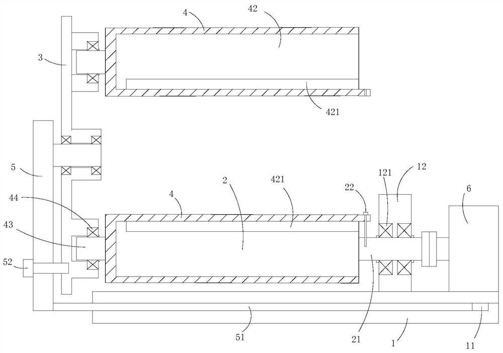
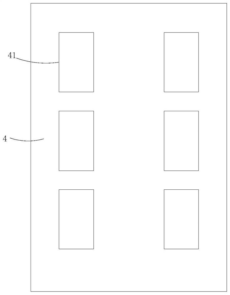
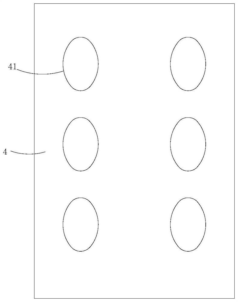
[0039] Such as Figure 1 to Figure 4 As shown, the present invention provides a mask roller cutting tool, comprising: a bottom plate 1, a drive roller shaft 2 is rotatably connected above the bottom plate 1; Slidingly arranged on one side of the driving roller shaft 2; a plurality of cutter sleeves 4, a plurality of cutter sleeves 4 are arranged on the rotating disk 3 at intervals along the circumferential direction of the rotating disk 3, The outer surface of each cutter sleeve 4 is provided with a blade 41, and a plurality of cutter sleeves 4 are switchably sleeved on the driving roller shaft 2, sleeved on the driving roller shaft A flow channel for cutting materials is defined between the cutter sleeve 4 on the 2 and the bottom plate 1 .
[0040] It can be understood that when the cutter sleeve 4 needs to be replaced, the rotating disk 3 can be moved to drive the cutter sleeve 4 to separate from the drive roller shaft 2, and then the rotating disk 3 can be rotated to make ...
Embodiment 2
[0045] The difference between this embodiment and the above-mentioned embodiments is that it also includes an adjustment frame, the adjustment frame includes a stand 5, the rotating disk 3 is rotatably connected to the stand 5, and the stand 5 is slidably arranged on the on base plate 1. It can be understood that, by rotating the rotating disk 3 and being arranged on the stand 5 , the rotation of the rotating disk 3 is more reliable, and it is convenient to replace the cutter sleeve 4 .
[0046] In some embodiments, the rotating disk 3 and the stand 5 are rotationally connected through bearings.
[0047]In some embodiments of the present invention, the bottom plate 1 is provided with a sliding groove 11 ; the stand 5 is provided with a sliding plate 51 , and the sliding plate 51 is slidably disposed in the sliding groove 11 . Thus, the slide plate 51 is slidably disposed in the slide groove 11 , so that the movement of the stand 5 is more reliable.
[0048] In some embodimen...
Embodiment 3
[0050] The difference between this embodiment and the above-mentioned embodiment is that each of the cutter sleeves 4 is provided with a positioning blind hole 42, and the inner surface of the positioning blind hole 42 is provided with a positioning protrusion 421, and the driving roller shaft 2 protrudes into the positioning blind hole 42, the driving roller shaft 2 is provided with a positioning groove, and the positioning protrusion 421 is arranged in the positioning groove.
[0051] It can be understood that, by making the positioning protrusion 421 extend into the positioning groove, the stability of the connection between the driving roller shaft 2 and the cutter sleeve 4 is ensured, so that the driving roller shaft 2 can drive the cutter sleeve 4 when rotating. Rotate to ensure the stability of material cutting.
[0052] In some embodiments of the present invention, it also includes a driving motor 6, the other side of the driving roller shaft 2 is provided with a conne...
PUM
 Abstract
Description
Claims
Application Information
 - R&D
- Intellectual Property
- Life Sciences
- Materials
- Tech Scout
- Unparalleled Data Quality
- Higher Quality Content
- 60% Fewer Hallucinations
Browse by: Latest US Patents, China's latest patents, Technical Efficacy Thesaurus, Application Domain, Technology Topic, Popular Technical Reports.
© 2025 PatSnap. All rights reserved.Legal|Privacy policy|Modern Slavery Act Transparency Statement|Sitemap|About US| Contact US: help@patsnap.com


