A kind of ultra-high molecular weight polymer shaped parts forming equipment with controllable orientation
A technology of ultra-high molecular weight and forming equipment, which is applied in the field of forming equipment for ultra-high molecular weight polymer special-shaped parts. It can solve problems such as not being able to meet high-end products, and achieve the effects of improving molding quality, ensuring stability, and improving overall performance.
- Summary
- Abstract
- Description
- Claims
- Application Information
AI Technical Summary
Problems solved by technology
Method used
Image
Examples
Embodiment 1
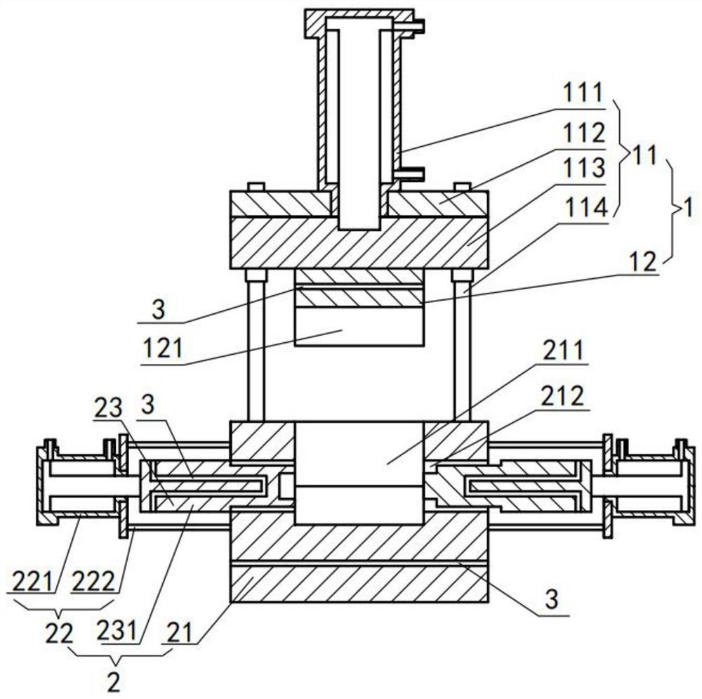
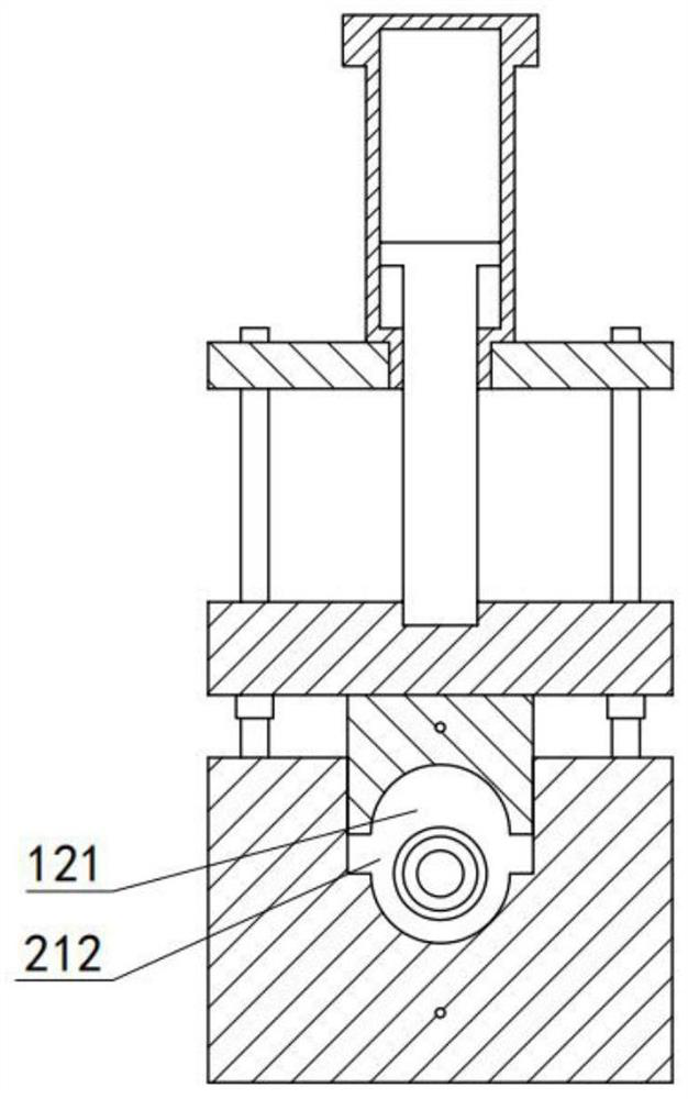
[0028] refer to Figure 1-2 As shown, the present invention discloses a molding equipment for ultra-high molecular weight polymer special-shaped parts with controllable orientation, including: a movable mold module 1 and a fixed mold module 2; the movable mold module 1 includes a vibration driving mechanism 11 and a movable mold 12; The movable die 12 is fixedly connected to the bottom end of the vibration drive mechanism 11; the fixed die module 2 includes a fixed die 21, two fixed die drive mechanisms 22 and two forming mechanisms 23; the upper end of the fixed die 21 is provided with a forming groove 211 with an upward opening. , and its outer side wall is provided with a through hole 212 matching the molding mechanism 23 ; the fixed mold 21 is located below the movable mold 12 ;
[0029] The molding mechanism 23 is a mold core 231 ; each mold core 231 is correspondingly disposed in a through hole 212 , and one end of the mold core 231 away from the molding groove 211 is fi...
Embodiment 2
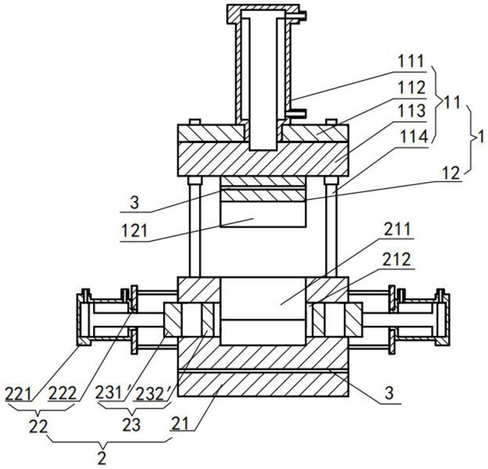
[0041] refer to image 3 As shown, the present invention discloses another ultra-high molecular weight polymer shaped part forming equipment with controllable orientation.
[0042] In this embodiment, the forming mechanism 23 is a mechanism composed of a limit block 231 ′ and a slider 232 ′; the limit block 231 ′ and the slider 232 ′ can be slidably arranged in the through hole 212 ; the slider 232 ' is closer to the forming groove 211 than the limit block 231'; one end of the limit block 231' away from the forming groove 211 is fixedly connected to the output end of the fixed die drive mechanism 22; There are two; two limit blocks 231 ′ and two sliding blocks 232 ′ are symmetrically arranged in the through holes 212 on both sides of the fixed die 21 , and the other structures are the same as those of the first embodiment.
[0043] Forming method: a. The driving device 221 drives the limiting block 231' to move to the inside of the forming groove 211, thereby driving the slid...
PUM
| Property | Measurement | Unit |
|---|---|---|
| viscosity | aaaaa | aaaaa |
| viscosity | aaaaa | aaaaa |
Abstract
Description
Claims
Application Information
 - R&D
- Intellectual Property
- Life Sciences
- Materials
- Tech Scout
- Unparalleled Data Quality
- Higher Quality Content
- 60% Fewer Hallucinations
Browse by: Latest US Patents, China's latest patents, Technical Efficacy Thesaurus, Application Domain, Technology Topic, Popular Technical Reports.
© 2025 PatSnap. All rights reserved.Legal|Privacy policy|Modern Slavery Act Transparency Statement|Sitemap|About US| Contact US: help@patsnap.com


