Extension printing and dyeing device

The technology of a deflecting device and a lifting device is applied in the field of printing and dyeing, which can solve the problems such as the inability to guarantee the printing and dyeing effect of fabrics, and achieve the effects of improving the service life, enhancing the buffer capacity and ensuring the printing and dyeing quality.

Active Publication Date: 2021-06-25
桐乡市金达染整科技股份有限公司
View PDF7 Cites 1 Cited by
  • Summary
  • Abstract
  • Description
  • Claims
  • Application Information

AI Technical Summary

Problems solved by technology

[0005] Aiming at the deficiencies of the prior art, the present invention provides an extended printing and dyeing device, which solves the problem that the existing printing and dyeing device cannot guarantee the printing and dyeing effect of the cloth, and can arrange the cloth during the printing and dyeing process, improve the quality of the cloth, and reduce the In order to prevent the damage to the fabric during the process of carding, it can automatically increase the printing and dyeing strength of the fabric when the printing and dyeing of the fabric is insufficient, ensure the printing and dyeing quality of the fabric, improve the flexibility of the device, and adjust the internal parts of the device during the printing and dyeing process The location is convenient for printing and dyeing, which enhances the buffering capacity of the device

Method used


Image

  • Extension printing and dyeing device
  • Extension printing and dyeing device
  • Extension printing and dyeing device

Examples


Embodiment 1

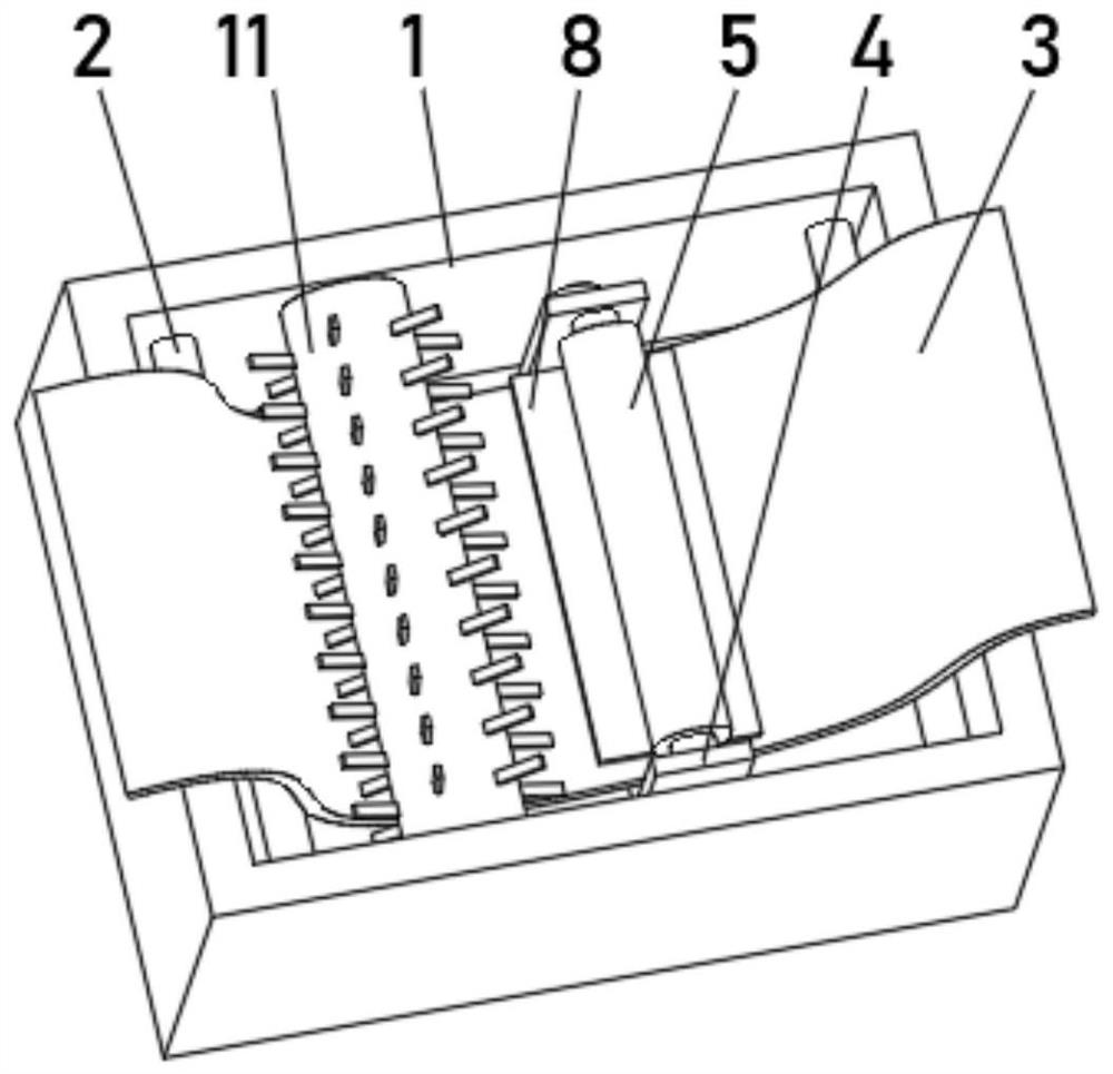
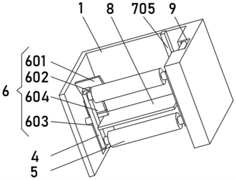
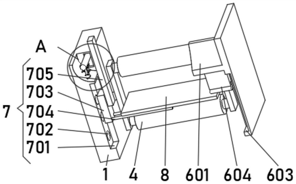
[0030] see Figure 1-3 , the present invention provides a technical solution: an extended printing and dyeing device, including a printing and dyeing barrel 1, a limit wheel 2 is symmetrically installed between the two sides of the inner wall of the printing and dyeing barrel 1, and a printing and dyeing cloth 3 is slidably connected to the outer side of the limit wheel 2, and the printing and dyeing An extension frame 4 is rotationally connected between both sides of the inner wall of the barrel 1, and an extension wheel 5 is installed symmetrically between the two sides of the extension frame 4, and a deflection device 6 is installed on one side of the inner wall of the printing and dyeing barrel 1, and the inner wall of the printing and dyeing barrel 1 is far away from the deflection A lifting device 7 is installed on one side of the device 6, and a trigger plate 8 is installed on the top of the lifting device 7.

[0031] The deflection device 6 includes an elastic plate 60...

Embodiment 2

[0035] see Figure 1-4 , the present invention provides a technical solution: on the basis of Embodiment 1, a buffer device 10 is installed inside the buffer tank 9, the buffer device 10 includes a shaft groove 101, and a shedding rod 102 is slidably connected between the two sides of the shaft groove 101 A buffer spring 103 is fixedly connected to the bottom of the inner side of the buffer groove 9 below the dropout rod 102 .

[0036] The bottom of the shedding rod 102 is fixedly connected with a support arc plate 104 , the bottom of the support arc plate 104 is fixedly connected with a positioning rod 105 , and the buffer spring 103 is sleeved on the outside of the positioning rod 105 .

[0037]During use, push the control lever 705 to one side, the control lever 705 squeezes the shedding rod 102 downwards, and drives the positioning rod 105 to squeeze the buffer spring 103 to buffer until the bottom of the shedding rod 102 contacts the buffer groove 9, which strengthens the...

Embodiment 3

[0039] see Figure 1-5 , the present invention provides a technical solution: on the basis of Embodiment 1, a carding roller 11 is rotatably connected between the two sides of the inner wall of the printing and dyeing barrel 1, and a carding device 12 is evenly installed on the outside of the carding roller 11.

[0040] The carding device 12 includes a carding groove 121, and one side of the inner wall of the carding groove 121 is uniformly equipped with carding rods 122.

[0041] One side of the combing rod 122 is rotatably connected with a protective rod 123, and the end of the protective rod 123 away from the combing rod 122 extends to the outside of the combing slot 121, and the end of the protective rod 123 away from the combing rod 122 is equipped with a metal ball 124.

[0042] When in use, when the printing and dyeing cloth 3 moves through the printing and dyeing barrel 1, it drives the carding roller 11 to rotate, and the protection bar 123 combs the texture of the pr...


PUM


Abstract

The invention discloses an extension printing and dyeing device. The extension printing and dyeing device comprises a printing and dyeing barrel; limiting wheels are symmetrically installed between the two sides of the inner wall of the printing and dyeing barrel; printing and dyeing cloth is slidably connected to the outer sides of the limiting wheels; an extension frame is rotatably connected between the two sides of the inner wall of the printing and dyeing barrel; extension wheels are symmetrically installed between the two sides of the extension frame; and a deflection device is mounted on one side of the inner wall of the printing and dyeing barrel. The invention relates to the technical field of printing and dyeing. According to the extension printing and dyeing device, the purpose of guaranteeing the printing and dyeing effect of cloth is achieved, the cloth can be tidied in the printing and dyeing process, the quality of the cloth is improved, damage to the cloth in the cloth carding process is reduced, the printing and dyeing strength of the cloth can be automatically improved when printing and dyeing of the cloth are insufficient, and the printing and dyeing quality of the cloth is guaranteed; and the flexible degree of the device is improved, the positions of internal parts of the device can be adjusted in the printing and dyeing process to facilitate printing and dyeing, and the buffering capacity of the device is enhanced.

Description

technical field [0001] The invention relates to the technical field of printing and dyeing, in particular to an extended printing and dyeing device. Background technique [0002] Printing and dyeing, also known as dyeing and finishing, is a processing method and a general term for pretreatment, dyeing, printing, finishing, washing, etc. [0003] However, the existing printing and dyeing devices cannot guarantee the printing and dyeing effect of the cloth. In the process of printing and dyeing, they do not have the function of finishing the cloth, and cannot reduce the damage to the cloth during the process of carding the cloth. The printing and dyeing strength and flexibility are poor, and the position of the internal parts of the device cannot be adjusted during the printing and dyeing process to facilitate printing and dyeing, and the buffering capacity is poor. Contents of the invention [0004] (1) Solved technical problems [0005] Aiming at the deficiencies of the ...

Claims


Application Information

Patent Timeline
Patent Type & Authority Applications(China)
IPC IPC(8): D06B3/10D06B23/02D06G1/00
CPCD06B3/10D06B23/02D06B23/026D06G1/00
Inventor 刘运通
Owner 桐乡市金达染整科技股份有限公司
Why Eureka
Try Eureka