Screw rotating device capable of automatically disengaging threads
A rotating device and screw technology, applied in the direction of transmission, slip coupling, belt/chain/gear, etc., can solve the problems of increased production cost and labor intensity, damage to the thread of the screw and slider, and screw rotation accuracy Difficult to control and other problems, to achieve the effect of convenient and effective connection, reduce distance installation accuracy, and ingenious and effective design
- Summary
- Abstract
- Description
- Claims
- Application Information
AI Technical Summary
Problems solved by technology
Method used
Image
Examples
Embodiment 1
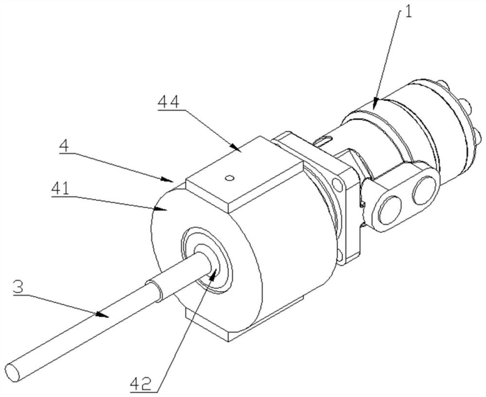
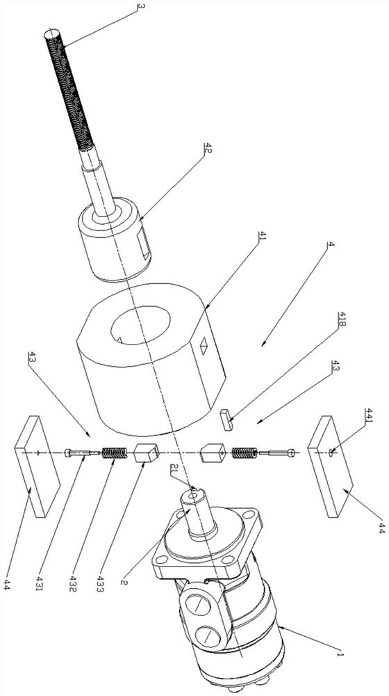
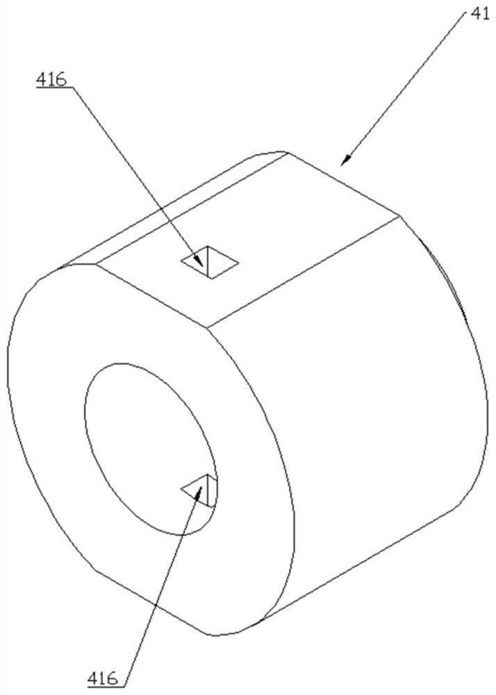
[0040] like Figure 1-9 As shown, this embodiment provides a screw rotating device for automatic detooth removal, including a motor 1, a transmission shaft 2 and a screw 3, and the transmission shaft 2 and the screw 3 are connected by an automatic detooth assembly 4, wherein the automatic detooth assembly 4 includes an outer sleeve 41 and an inner sleeve 42, the outer sleeve 41 is fixedly connected to the transmission shaft 2, the screw rod 3 is fixedly connected to the inner sleeve 42, the outer sleeve 41 is set outside the inner sleeve 42 and relatively fixedly connected through the elastic member 43; In a normal state, the motor 1 drives the transmission shaft 2 to rotate, which sequentially drives the outer sleeve 41, the inner sleeve 42, and the screw 3 to rotate synchronously. When the rotation of the screw 3 is limited, the inner sleeve 42 and the outer sleeve 41 are out of the fixed connection state , the outer sleeve 41 can slide and rotate outside the inner sleeve 42...
Embodiment 2
[0060] like Figure 10-11 , Compared with the first embodiment, the difference between this embodiment is the connection method between the outer sleeve 41 and the transmission shaft 2 . In this embodiment, the end of the transmission shaft 2 is provided with a shaft end through hole (not shown in the figure), the coupling section 411 is provided with a radial coupling through hole 415 correspondingly, and the pin rod 419 is provided to pass through the shaft end The through hole and the coupling through hole 415 are used to realize the axial and circumferential fixed coupling of the transmission shaft 2 and the outer sleeve 41 . The pressure plate 44 can be additionally installed on the outer sleeve 41 by screws, and the outer sleeve 41 is provided with a flat surface to facilitate the installation of the pressure plate; when the transmission shaft 2 and the outer sleeve 41 are connected by pins, the pin 419 can be provided with threads, and the pressure plate Corresponding ...
Embodiment 3
[0063] This embodiment provides a specific application scenario of the screw rotating device for automatic tooth extraction.
[0064] like Figure 12-13 As shown in the figure, in this embodiment, the screw rotating device for automatic tooth removal is applied in the field of mold processing, but it is not limited to this field. To be connected, it is necessary to rotate the screw 3 to drive the insertion device 6 to move forwards and backwards as a whole, so that other components connected to the insertion device 6 can move forwards and backwards to assemble with the main device 9 .
[0065] The mounting seat 5 is an annular structure with an inner circle and an outer square, and the middle part is an axial mounting through hole 51. The mounting seat 5 is provided with a mounting screw hole 52 corresponding to the motor 1. The mounting seat 5 and the motor 1 are fixedly connected by bolts. 2 is connected to the automatic tooth removal assembly 4 through the installation thr...
PUM
 Abstract
Description
Claims
Application Information
 - R&D
- Intellectual Property
- Life Sciences
- Materials
- Tech Scout
- Unparalleled Data Quality
- Higher Quality Content
- 60% Fewer Hallucinations
Browse by: Latest US Patents, China's latest patents, Technical Efficacy Thesaurus, Application Domain, Technology Topic, Popular Technical Reports.
© 2025 PatSnap. All rights reserved.Legal|Privacy policy|Modern Slavery Act Transparency Statement|Sitemap|About US| Contact US: help@patsnap.com


