Visible light sparse array waveguide optical phased array

A waveguide optics, sparse array technology, applied in optics, nonlinear optics, radio wave measurement systems, etc., can solve the problem of small scanning angle of radar

Pending Publication Date: 2021-06-25
PENG CHENG LAB
View PDF6 Cites 1 Cited by
  • Summary
  • Abstract
  • Description
  • Claims
  • Application Information

AI Technical Summary

Problems solved by technology

[0004] The main purpose of the present invention is to provide a visible light sparse array waveguide optical phased array, optimize the array element distribution in the waveguide optical phased array through the sparse array, and expand the optical phased array under the condition of meeting the integration requirements of device miniaturization The scanning angle of the antenna is designed to solve the technical problem that the existing waveguide optical phased array radar scanning angle is too small

Method used


Image

  • Visible light sparse array waveguide optical phased array
  • Visible light sparse array waveguide optical phased array
  • Visible light sparse array waveguide optical phased array

Examples


Embodiment Construction

[0029] It should be understood that the specific embodiments described here are only used to explain the present invention, not to limit the present invention.

[0030] At present, the existing lidar is sufficient to work in the visible light band. However, due to the limited scanning angle of the optical phased array in the lidar, when the lidar works in the visible light band, grating lobes often appear, and the scanning angle is small. . Based on the above problems, this embodiment provides a visible light sparse array waveguide optical phased array, which can be applied to laser radars working in the visible light band to improve the scanning field of view of laser radars, especially in the application scenarios of visible light. Radar grating lobe problem, to achieve large field of view scanning.

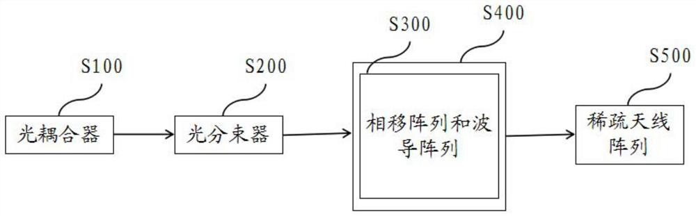
[0031] refer to figure 1 , figure 1 It is a schematic structural diagram of a visible light sparse array waveguide optical phased array provided by an embodiment of the pres...


PUM


Abstract

The invention discloses a visible light sparse array waveguide optical phased array. The visible light sparse array waveguide optical phased array comprises an optical coupler used for carrying out coupling processing on an obtained optical signal, a light beam splitter used for carrying out light splitting processing on the coupled light signals to obtain sub-signals, a phase shift array connected with the light beam splitter and used for regulating and controlling the phases of the sub-signals to obtain target sub-signals, a waveguide array used for transmitting the coupled optical signal, the sub-signal and the target sub-signal, and a sparse antenna array connected with the phase shift array and used for scattering the target sub-signals to a free space. The array elements of the optical phased array are optimized through the sparse array, the grating lobe problem of the optical phased array in the visible light wave band is solved, and large-view-field scanning is achieved.

Description

technical field [0001] The invention relates to the field of optoelectronic devices, in particular to a visible light sparse array waveguide optical phased array. Background technique [0002] Traditional commercial laser radars generally scan by mechanical rotation. The system is complex, the scanning speed is slow, and the weight and volume are large, which is not conducive to integration, so it cannot meet the requirements of device miniaturization. The scanning speed of liquid crystal phased array radar is slow, which is not conducive to integration and cannot meet the needs of device miniaturization. Although the optical phased array based on MEMS has a fast scanning speed, the scanning angle is limited. The waveguide optical phased array radar has a fast scanning speed and can achieve high integration. It is the most promising all-solid-state lidar solution. [0003] At present, the optical phased array radar based on silicon-on-insulator can only work at wavelengths...

Claims


Application Information

Patent Timeline
IPC IPC(8): G02F1/29G02F1/295G01S7/481
CPCG02F1/292G02F1/2955G01S7/4817
Inventor 孙彩明邓舒鹏张爱东
Owner PENG CHENG LAB
Why Eureka
Try Eureka