
Thermal cycle temperature control system based on electric refrigeration technology

A technology of temperature control system and thermal cycle, applied in the direction of control/regulation system, non-electric variable control, temperature control, etc. Problems such as power drive, rapid heating and cooling and repeated thermal cycles, etc., to achieve the effect of low power drive efficiency and preventing condensation backflow

Pending Publication Date: 2021-06-25
XIAMEN UNIV
View PDF6 Cites 2 Cited by
  • Summary
  • Abstract
  • Description
  • Claims
  • Application Information

AI Technical Summary

Problems solved by technology

[0003] At present, the temperature control part of most PCR detector products in China cannot realize the functions of high-power drive, rapid heating and cooling, and repeated thermal cycles for the control of semiconductor refrigerators, and does not have the response speed, accuracy and quality required for PCR detection. Efficiency and other temperature control technical indicators, the actual operating current of semiconductor refrigeration chips is low, the number of temperature cycles is small, and the temperature control process is easy to burn and damage, resulting in the mainstream products in this part of the medical device market mainly relying on imports

Method used


Image

  • Thermal cycle temperature control system based on electric refrigeration technology
  • Thermal cycle temperature control system based on electric refrigeration technology
  • Thermal cycle temperature control system based on electric refrigeration technology

Examples


Embodiment Construction

[0030] The present invention will be further described below through specific embodiments.

[0031] In the present invention, the terms "first", "second", "third" and so on are only used to distinguish similar objects, and are not necessarily used to describe a specific order or sequence, nor can they be interpreted as indicating or implying relative importance sex. In the description, the orientations or positional relationships indicated by "up", "down", "left", "right", "front" and "rear" are based on the orientations or positional relationships shown in the drawings, and are only In order to facilitate the description of the present invention, it does not indicate or imply that the referred device must have a specific orientation, be constructed and operated in a specific orientation, and thus should not be construed as limiting the protection scope of the present invention. Those of ordinary skill in the art can understand the specific meanings of the above terms in this...


PUM


Abstract

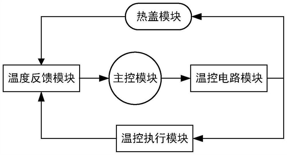
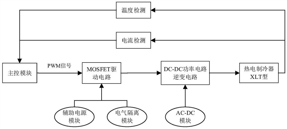
A thermal cycle temperature control system based on a thermoelectric refrigeration technology comprises a main control module, a temperature control circuit module, a temperature control execution module, a feedback module and a thermal cover module. The temperature control execution module is provided with a thermoelectric refrigerating unit and a sample groove, and the thermoelectric refrigerating unit is located below the sample groove for heating and refrigerating; the temperature control circuit module is connected with the temperature control execution module so as to drive the thermoelectric refrigerating unit, perform current commutation and control temperature rising and falling circulation; the heat cover module is arranged above the sample groove to prevent the sample from condensing and reflowing; the feedback module is connected with the temperature control execution module and the heat cover module so as to detect the temperature and convert a feedback signal into a voltage signal; and the main control module is connected with the feedback module and the temperature control circuit module so as to modulate a PWM control signal according to a PI control algorithm and current feedback so as to regulate and control the temperature control circuit module. According to the invention, high-power driving, rapid heating and cooling, wide-range temperature difference, high-efficiency operation and high-precision circulation of the thermoelectric refrigerating unit can be realized.

Description

technical field [0001] The invention relates to the field of temperature control of medical equipment, in particular to a thermal cycle temperature control system based on thermoelectric refrigeration technology. Background technique [0002] In key fields such as medical equipment, communication electronics, and aviation industry, temperature control systems are very important technical indicators and bottlenecks in technology research and development, especially medical equipment products such as real-time quantitative PCR instruments and gene sequencers that are widely in demand in the market. The PCR gene amplification reaction needs to achieve denaturation (94°C), annealing (55°C), and extension (72°C) three temperature cycles repeated dozens of times to complete the in vitro replication of DNA. Therefore, the reaction temperature environment of this type of product requires a wide range, rapid rise and fall, repeated cycles, and stable operation. This temperature contr...

Claims


Application Information

Patent Timeline
IPC IPC(8): G05D23/20
CPCG05D23/20
Inventor 张建寰高爽
Owner XIAMEN UNIV
Learn More