Calibration device and method and depth camera

A calibration device and a calibration method technology, applied in the field of computer vision, can solve problems such as the complexity of the calibration process, and achieve the effects of simplifying the calibration process, improving computing efficiency, and simplifying acquisition

Pending Publication Date: 2021-06-25
SHENZHEN ORBBEC CO LTD
View PDF7 Cites 2 Cited by
  • Summary
  • Abstract
  • Description
  • Claims
  • Application Information

AI Technical Summary

Problems solved by technology

[0004] The embodiment of the present application provides a calibration device, method, and depth camera. The method can determine the internal parameters of the camera through the first calibration image captured by the camera on the calibration plate; control the projection component to pattern the calibration plate The projection of the light beam, and then the second calibration image taken by the camera to the calibration plate, to determine the external parameters of the camera and the projection component. Compared with the calibration process of the relevant parameters of the camera in the prior art, this method controls the moving components. Obtaining the first calibration image and the second calibration image including the patterned light beam projected by the projection part on the calibration plate on the calibration plate at different positions simplifies the acquisition of calibration materials, and because the f

Method used


Image

  • Calibration device and method and depth camera
  • Calibration device and method and depth camera
  • Calibration device and method and depth camera

Examples


Embodiment 1

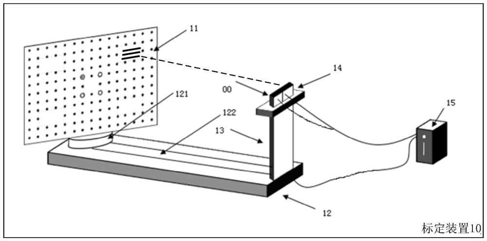
[0032] figure 1A schematic structural diagram of a calibration device 10 provided by an embodiment of the present application is shown, the calibration device 10 is used to calibrate a camera 00, and the calibration device 10 includes a calibration board 11, a moving part 12, a fixed bracket 13, a projection part 14 and a processor 15, the calibration plate 11 is fixed on the moving part 12, and the moving part 12 is used to change the position of the calibration plate 11; the camera 00 and the projection part 14 are fixed on the fixed bracket 13, so that the shooting of the camera 00 The picture includes the calibration plate 11; the processor 15 is electrically connected to the moving part 12 and the camera 00, and is used to receive the first calibration image and the second calibration image collected from the camera 00, and the processor 15 is also used to control The moving part 12 moves, and the internal parameters of the camera 00 and the external parameters of the cam...

Embodiment 2

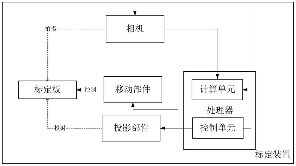
[0039] The present application also provides a calibration method. In this embodiment, the process of the above calibration method is executed by a calibration device. The calibration device 10 includes a calibration board 11, a moving part 12, a fixed support 13, a projection part 14 and a processor 15, and the interconnection relationship between each part can be referred to the relevant description of the previous embodiment, and the calibration device 10 can execute the present invention. The calibration method provided by the application.

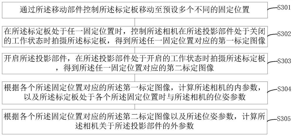
[0040] image 3 It shows the implementation flowchart of the calibration method provided by the first embodiment of the application, which is applied to figure 1 The calibration device 10 shown is described in detail as follows:

[0041] S301: Using the moving component to control the calibration plate to move to a plurality of different preset fixed positions.

[0042] In this embodiment, the calibration device can adjust the pose ...


PUM


Abstract

The invention is suitable for the field of machine vision, and provides a calibration device and method and a depth camera, the device comprises a calibration plate, a moving part, a fixed support, a projection part, a camera and a processor; the calibration plate is provided with feature points and positioning information; the projection part is used for projecting the patterned light beam onto the calibration plate; the moving part is used for changing the position of the calibration plate; the camera and the projection component are fixed on the fixed bracket, and the camera is used for collecting the patterned light beam reflected by the calibration plate and generating a calibration image; and the processor is electrically connected with the moving part and the camera, and is used for receiving the calibration image acquired by the camera, controlling the moving part to move, and determining the internal parameters of the camera and the external parameters of the camera and the projection part based on the calibration image. The calibration images of the calibration plate at different positions are obtained by controlling the moving part, acquisition of the calibration material is simplified, and therefore the calibration process of relevant parameters of the camera is simplified.

Description

technical field [0001] The present application belongs to the field of computer vision, and in particular relates to a calibration device, method and depth camera. Background technique [0002] A series of depth cameras such as monocular structured light cameras and TOF cameras are composed of a projection part and a camera. In order to achieve accurate depth measurement, it is usually necessary to strictly restrict the relative posture of the projection part and the camera so that the optical axis of the camera and the two constitute baselines are perpendicular to each other. However, errors are inevitable in the actual assembly process. If the depth is calculated directly according to the depth calculation method under the ideal attitude, the measurement accuracy of the depth camera will be reduced. Therefore, it is necessary to calibrate the depth camera to obtain the accurate attitude between the projection part and the camera, that is, the external parameters of the ca...

Claims


Application Information

Patent Timeline
IPC IPC(8): G06T7/80
CPCG06T7/85G06T2207/30244Y02P70/50
Inventor 兰富洋王兆民杨鹏
Owner SHENZHEN ORBBEC CO LTD
Why Eureka
Try Eureka