Optical fiber route detection system and corresponding route detection method

A detection system and optical fiber technology, which is applied in the field of optical fiber routing detection system, can solve problems such as operation hazards, optical fiber damage, and staff injuries, and achieve the effects of improving survey efficiency, reducing personal injury risks, and reducing optical cable damage

Active Publication Date: 2021-06-25
QUALSEN (GUANGZHOU) TECH CO LTD
View PDF9 Cites 1 Cited by
  • Summary
  • Abstract
  • Description
  • Claims
  • Application Information

AI Technical Summary

Problems solved by technology

[0005] In addition, when identifying optical fibers, the handheld device also has the following problems in the positioning of optical fibers: 1) The amount of engineering is large: all optical cables need to be inspected, and the same repeated inspections are performed on all optical cables. The same number of optical fibers to be tested will be repeatedly tested; 2) Operation hazard: Since the operator needs to use the optical fiber identification instrument to detect the ODF rack, the staff needs to perform the detection in a complex line environment, which may cause the staff to be injured; 3) Damaged optical cable: In the process of using the optical fiber identifier, it is very easy to cause problems such as broken ribs of the optical cable and damage to the optical fiber. Therefore, it is not recommended to use this method in engineering under non-essential conditions.

Method used


Image

  • Optical fiber route detection system and corresponding route detection method
  • Optical fiber route detection system and corresponding route detection method

Examples


Embodiment Construction

[0026] In the following description, specific details such as specific system structures and technologies are presented for the purpose of illustration rather than limitation, so as to thoroughly understand the embodiments of the present invention. It will be apparent, however, to one skilled in the art that the invention may be practiced in other embodiments without these specific details. In other instances, detailed descriptions of well-known systems, devices, circuits, and methods are omitted so as not to obscure the description of the present invention with unnecessary detail.

[0027]It should be understood that when used in this specification and the appended claims, the term "comprising" indicates the presence of described features, integers, steps, operations, elements and / or components, but does not exclude one or more other features. , whole, step, operation, element, component and / or the presence or addition of a collection thereof.

[0028] It should also be unde...


PUM


Abstract

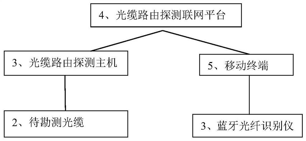
The embodiment of the invention provides a method for identifying a target optical cable in multiple optical cables and a corresponding system, and the method is cooperatively implemented by an optical cable route detection networking platform, an optical fiber route detection host, a to-be-surveyed optical cable, an optical fiber identification instrument and a mobile terminal, and the optical fiber identification instrument is arranged in an optical fiber distribution frame and is connected with the to-be-surveyed optical cable, and is used for reading a code, used for identifying a port, of a chip on the port of the optical fiber, and transmitting the read data to the optical cable routing detection networking platform in a Bluetooth communication mode. The mobile terminal stores a database about identification information conditions of ports of optical fibers in an optical cable to be surveyed, and is used for receiving data about codes on optical fiber port chips transmitted by the optical cable route detection networking platform and comparing the data with data in the database to judge whether a matching condition exists or not, and if yes, the route of the optical fiber can be judged. According to the optical cable routing survey system and the corresponding method, the optical cable routing survey efficiency is improved: 1) equipment is installed in advance; 2) the personal injury risk of operators is reduced; and 3) continuous detection is not needed.

Description

technical field [0001] The invention relates to the field of optical fiber routing detection, in particular to an optical fiber routing detection system and a corresponding routing detection method. Background technique [0002] As a signal transmission channel, the optical cable line is the core component of the optical fiber communication system. According to statistics, as of the first half of 2017, the total length of national optical cable lines reached 34.06 million kilometers, and the proportions of access network optical cables, local network relay optical The trend of "optical into copper and out" of ingress ports is more obvious, and the proportion of optical fiber access ports reaches 81.0%. According to the plan announced by the Ministry of Industry and Information Technology and the National Development and Reform Commission, by 2018, national broadband coverage will be expanded to 90%. [0003] Among the failures of optical fiber communication systems, line f...

Claims


Application Information

Patent Timeline
Patent Type & Authority Applications(China)
IPC IPC(8): H04B10/077H04Q11/00
CPCH04B10/0773H04Q11/0062H04Q2011/0073H04Q2011/0083
Inventor 罗丁元陈雄颖蔡俊刘振河梁钢兴李英乐李德炎刘德良严景
Owner QUALSEN (GUANGZHOU) TECH CO LTD
Why Eureka
Try Eureka