Perforating device for adding protection plate and pasting adhesive tape on PCB production line

A technology for printed circuit boards and punching devices, which is applied in the fields of printed circuits, printed circuit manufacturing, mechanical/acoustic circuit processing, etc. close together and improve work efficiency

Active Publication Date: 2021-06-25
湖北瀚鼎电路电子有限公司
View PDF6 Cites 3 Cited by
  • Summary
  • Abstract
  • Description
  • Claims
  • Application Information

AI Technical Summary

Problems solved by technology

[0003] In the prior art, the protective board is manually placed on the PCB printed circuit board, and then the protective board is manually pasted with adhesive tape to fix it, and then the punching equipment automatically punches holes on the PCB printed circuit board,

Method used


Image

  • Perforating device for adding protection plate and pasting adhesive tape on PCB production line
  • Perforating device for adding protection plate and pasting adhesive tape on PCB production line
  • Perforating device for adding protection plate and pasting adhesive tape on PCB production line

Examples


Embodiment 1

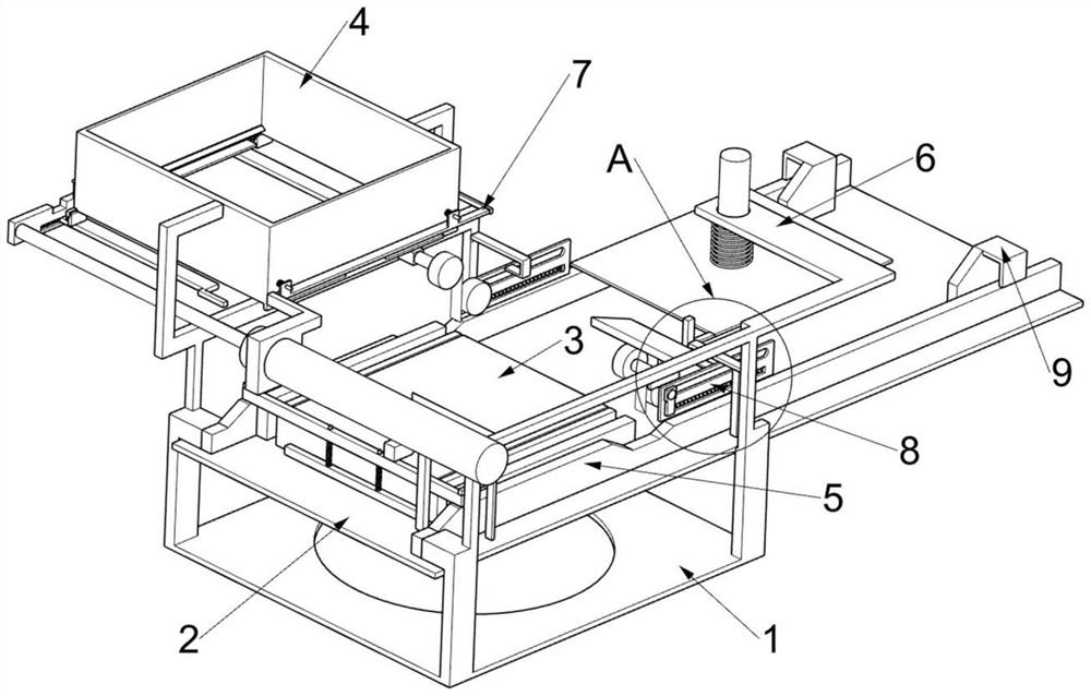
[0029] A punching device for adding a protective plate and pasting adhesive tape on a PCB printed circuit board production line, such as Figure 1-11 As shown, it includes a support frame 1, a conveyor belt 2, a placement plate 3, a lower plate mechanism 4, a glue cutting mechanism 5, and a punching mechanism 6. The conveyor belt 2 is set on the support frame 1, and the conveyor belt 2 is used to convey the circuit. Plate, the top of the conveyor belt 2 is provided with a placement plate 3, the lower plate mechanism 4 is set on the support frame 1, the lower plate mechanism 4 is used to intermittently put the protective plate, the glue cutting mechanism 5 is set on the support frame 1, and the glue The cutting mechanism 5 is used to paste the adhesive tape on the protective plate and peel off the adhesive tape. The punching mechanism 6 is arranged on the support frame 1 and is used to punch holes on the circuit board.

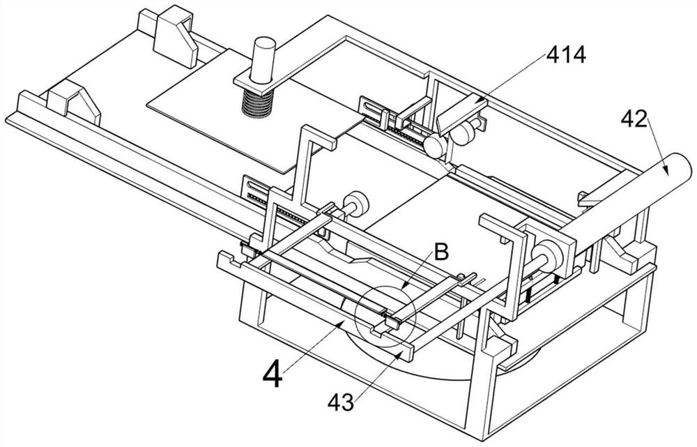
[0030]The lower plate mechanism 4 includes a protective p...

Embodiment 2

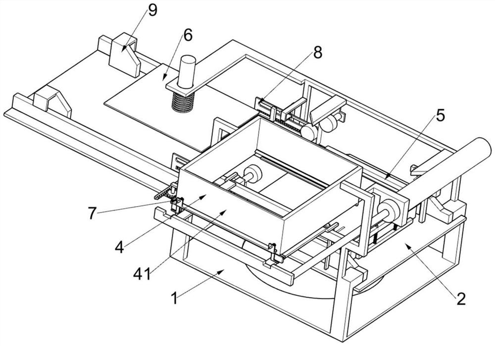
[0036] On the basis of Example 1, such as Figure 9 As shown, a control board device 7 is also included, and the control board device 7 is arranged on the protection board frame 41. The control board device 7 includes a sliding frame 71, a second slide bar 72, a fourth return spring 73, and a first rack 74. , the fourth fixed plate 75, gear 76, the second rack 77 and the fifth fixed plate 78, both sides of the protective plate frame 41 are provided with two second slide bars 72, wherein the two second slide bars 72 are jointly slidably connected There is a sliding frame 71, and a fifth fixed plate 78 is slidably connected to the other two second sliding bars 72. Through the mutual cooperation between the sliding frame 71 and the fifth fixed plate 78, the protective plate falls to the second rotating plate, so that A fourth return spring 73 is connected between the sliding frame 71 and the protection plate frame 41, and the fourth return spring 73 is used to drive the sliding f...

Embodiment 3

[0039] On the basis of Example 2, such as Figure 11 As shown, a rolling device 8 is also included, and the rolling device 8 is used to make the adhesive tape on the protection board and the protection board more fit, the rolling device 8 is arranged on the support frame 1, and the rolling device 8 includes a fixed frame 81 , slide block 82, second fixed rod 83, turning roller 84 and the 5th back-moving spring 85, support frame 1 is provided with fixed mount 81, on the fixed mount 81 sliding type is connected with the second fixed rod 83, the second fixed rod 83 One end is fixedly connected with a slide block 82, and the slide block 82 is used to drive the second fixed rod 83 and its upper device to move towards the direction close to the rubber stripping block 9. The other end of the second fixed rod 83 is rotatably connected with a rotating roller 84, and the rotating roller 84 is used for pressing the adhesive tape on the protective plate, and the fifth return spring 85 is ...


PUM


Abstract

The invention relates to a perforating device, in particular to a perforating device for adding a protection plate and pasting an adhesive tape on a PCB production line. The device comprises a supporting frame, a conveying belt, a containing plate, a plate discharging mechanism and the like, wherein the conveying belt is arranged on the supporting frame, the containing plate is arranged at the top of the conveying belt, the plate discharging mechanism is arranged on the supporting frame, an adhesive tape cutting mechanism is arranged on the supporting frame, and a perforating mechanism is arranged on the supporting frame. According to the invention, through mutual cooperation of an adhesive tape cutting mechanism, a rolling device and an adhesive tape uncovering block, an adhesive tape on an adhesive tape roll can be cut after a certain length is reserved, and then the adhesive tape pasted on a protection plate is uncovered through the adhesive tape uncovering block, so that a PCB is conveniently perforated, and the purposes of automatically pasting the adhesive tape on the protection plate, cutting the adhesive tape, uncovering the pasted adhesive tape and intermittently putting the protection plate are achieved.

Description

technical field [0001] The invention relates to a punching device, in particular to a punching device for adding a protective plate and sticking adhesive tape on a PCB printed circuit board production line. Background technique [0002] PCB printed circuit board is an important electronic component and the carrier of electrical connection of electronic components. After electronic equipment adopts PCB printed circuit board, due to the consistency of similar printed circuit boards, it avoids manual wiring errors and can realize Automatic insertion or placement, automatic soldering, and automatic detection of electronic components ensure the quality of electronic equipment, improve labor productivity, reduce costs, and facilitate maintenance. In the process of processing PCB printed circuit boards, they must be Drilling, add a protective plate before drilling, and then stick the tape. [0003] In the prior art, the protective board is manually placed on the PCB printed circui...

Claims


Application Information

Patent Timeline
IPC IPC(8): H05K3/00B26D9/00
CPCH05K3/00H05K3/0044B26D9/00H05K2203/02H05K2203/0228H05K2203/0221
Inventor 魏思良
Owner 湖北瀚鼎电路电子有限公司
Why Eureka
Try Eureka