
Control method of liquid cooling electric energy system, liquid cooling electric energy system and storage medium

A control method and electric energy technology, applied in electrical components, structural parts of electrical equipment, cooling/ventilation/heating renovation, etc. high power problems

Active Publication Date: 2021-06-25
上海桁壹高科技有限公司
View PDF12 Cites 0 Cited by
  • Summary
  • Abstract
  • Description
  • Claims
  • Application Information

AI Technical Summary

Problems solved by technology

[0002] Some current power equipment, such as electric vehicle charging stations, unmanned vehicle charging piles, solar inverters and other equipment, have a large heat dissipation. Currently, air cooling is used for heat dissipation, and the energy density has an upper limit. The heat dissipation is not enough to meet the cooling requirements, which limits the use scenarios of the equipment; in addition, some power equipment has very low power in standby state and very high power when in use, so the air-cooled heat dissipation method cannot be well adapted

Method used


Image

  • Control method of liquid cooling electric energy system, liquid cooling electric energy system and storage medium
  • Control method of liquid cooling electric energy system, liquid cooling electric energy system and storage medium
  • Control method of liquid cooling electric energy system, liquid cooling electric energy system and storage medium

Examples


Embodiment 2

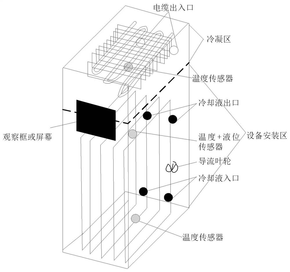
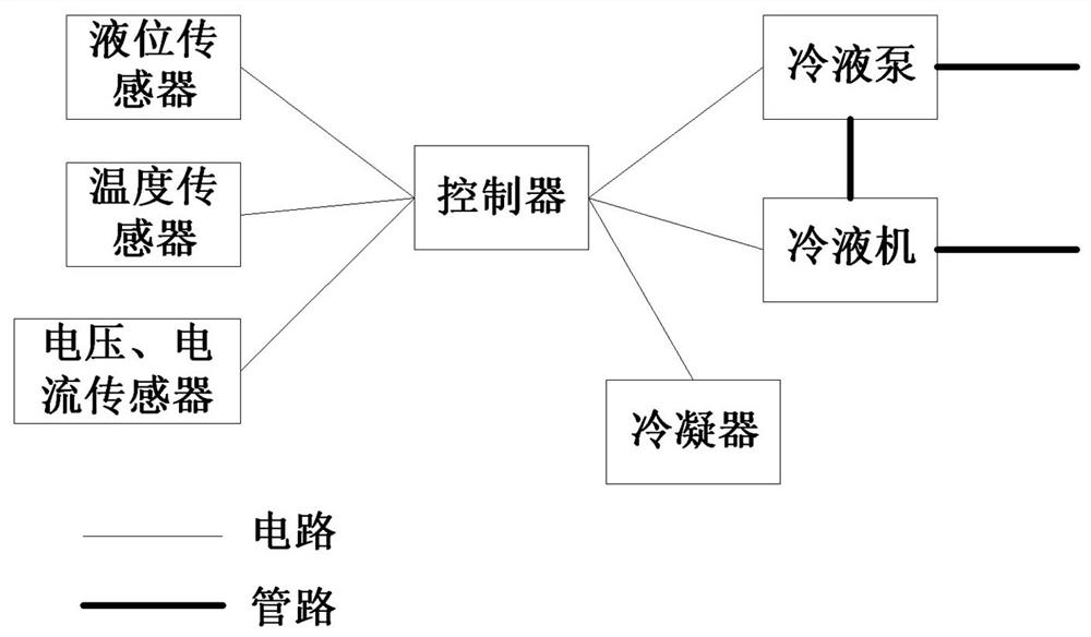
[0061] This embodiment also provides a liquid-cooled power system, such as figure 2 and image 3 As shown, the liquid-cooled power system includes: the equipment installation area and the condensation area located above the equipment installation area. Liquid machine, the cooling liquid pump communicates with the cooling liquid outlet end of the equipment installation area through the pipeline, and the cooling liquid machine communicates with the cooling liquid inlet end of the equipment installation area through the pipeline; the condensation area includes At least one set of condensers; the liquid-cooled power system also includes a controller, the controller is electrically connected to the cooling liquid pump, the cooling machine and the condenser; the controller is used to realize the control method of the liquid-cooled power system described in the above embodiments The steps are not repeated here.

[0062] In this embodiment, the liquid-cooled power system further in...


PUM


Abstract

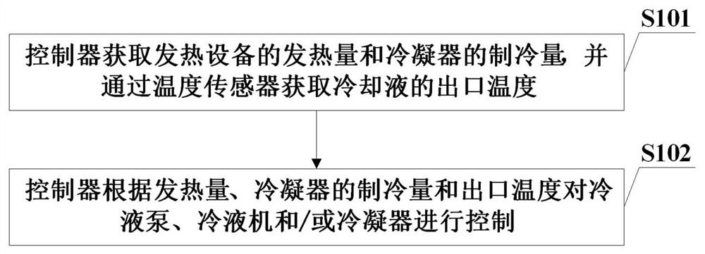
The invention relates to a control method of a liquid cooling electric energy system, the liquid cooling electric energy system and a storage medium. The system comprises an equipment installation area and a condensation area located above the equipment installation area, wherein the equipment installation area comprises cooling liquid and heating equipment immersed in the cooling liquid. The system further comprises a cooling liquid pump and a cooling liquid machine connected with the cooling liquid pump. The cooling liquid pump is communicated with the cooling liquid outlet end through a pipeline, and the cooling liquid machine is communicated with the cooling liquid inlet end through a pipeline. The condensation area comprises at least one group of condensers. The system also comprises a controller, and the controller is respectively connected with the cooling liquid pump, the cooling liquid machine and the condenser. The method comprises the steps that a controller obtains the heating value of heating equipment and the refrigerating capacity of a condenser, and obtains the outlet temperature of cooling liquid through a temperature sensor; and the controller controls the cooling liquid pump, the cooling liquid machine and / or the condenser according to the heating value, the refrigerating capacity of the condenser and the outlet temperature, the cooling efficiency is further improved by using an evaporative and immersed combined cooling mode, and the corresponding cooling mode is controlled to reduce the refrigeration energy consumption.

Description

technical field [0001] The invention relates to the field of cooling, in particular to a control method of a liquid-cooled electric energy system, a liquid-cooled electric energy system and a storage medium. Background technique [0002] Some current power equipment, such as electric vehicle charging stations, unmanned vehicle charging piles, solar inverters and other equipment, have a large heat dissipation. Currently, air cooling is used for heat dissipation, and the energy density has an upper limit. The heat dissipation is not enough to meet the cooling requirements, which limits the use scenarios of the equipment; in addition, some electric equipment has very low power in standby state and very high power when in use, so the air-cooled heat dissipation method cannot be well adapted. Contents of the invention [0003] The technical problem to be solved by the present invention is to provide a control method of a liquid-cooled electric energy system, a liquid-cooled ele...

Claims


Application Information

Patent Timeline
Patent Type & Authority Applications(China)
IPC IPC(8): H05K7/20
CPCH05K7/20936H05K7/20945H05K7/20318H05K7/20327H05K7/20381H05K7/203
Inventor 侯枕岍
Owner 上海桁壹高科技有限公司
Learn More