
Rolling element having sensor for use in rolling-element bearing

A technology for rolling bearings and rolling elements, which is applied in rolling contact bearings, bearings with rotational motion, bearings, etc., can solve problems such as low precision and limited resolution, and achieve the effects of improved precision, high-quality measurement results, and extended life

Pending Publication Date: 2021-06-25
THYSSENKRUPP ROTHE ERDE +1
View PDF10 Cites 2 Cited by
  • Summary
  • Abstract
  • Description
  • Claims
  • Application Information

AI Technical Summary

Problems solved by technology

Finally, capacitive load measurements are less accurate and have very limited resolution

Method used


Image

  • Rolling element having sensor for use in rolling-element bearing
  • Rolling element having sensor for use in rolling-element bearing
  • Rolling element having sensor for use in rolling-element bearing

Examples


Embodiment Construction

[0049] In the different figures, identical components are always provided with the same reference numerals and are therefore usually also named or mentioned only once in each case.

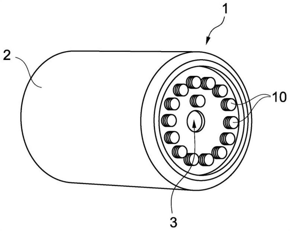
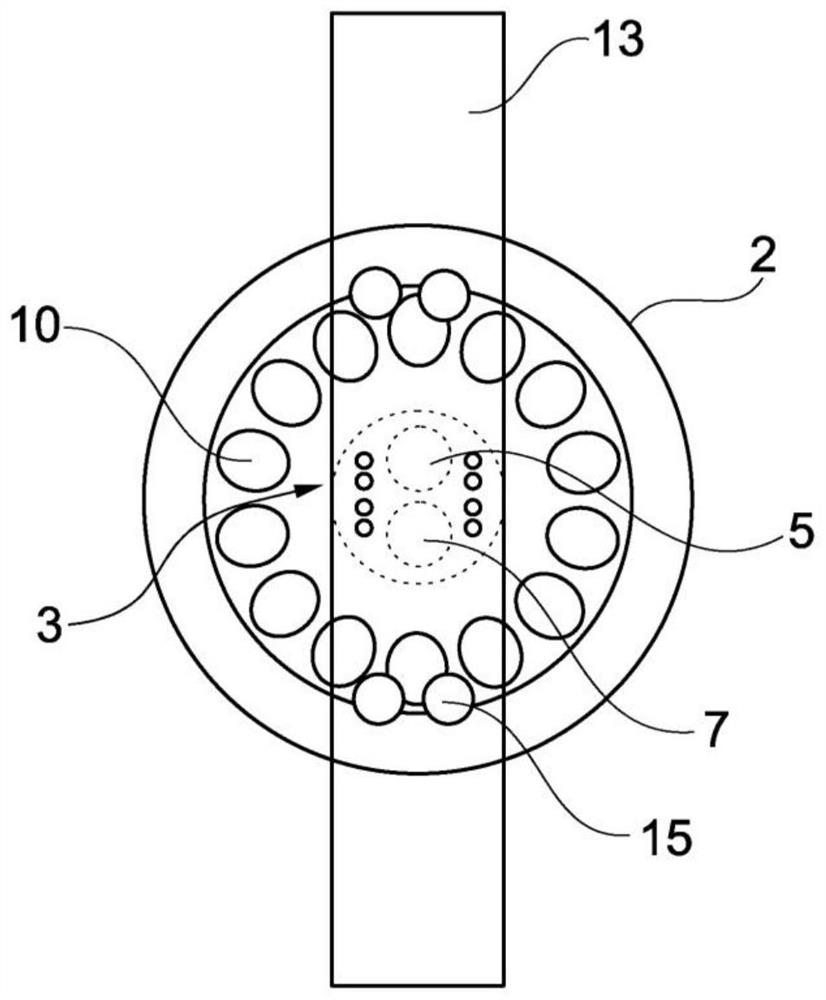
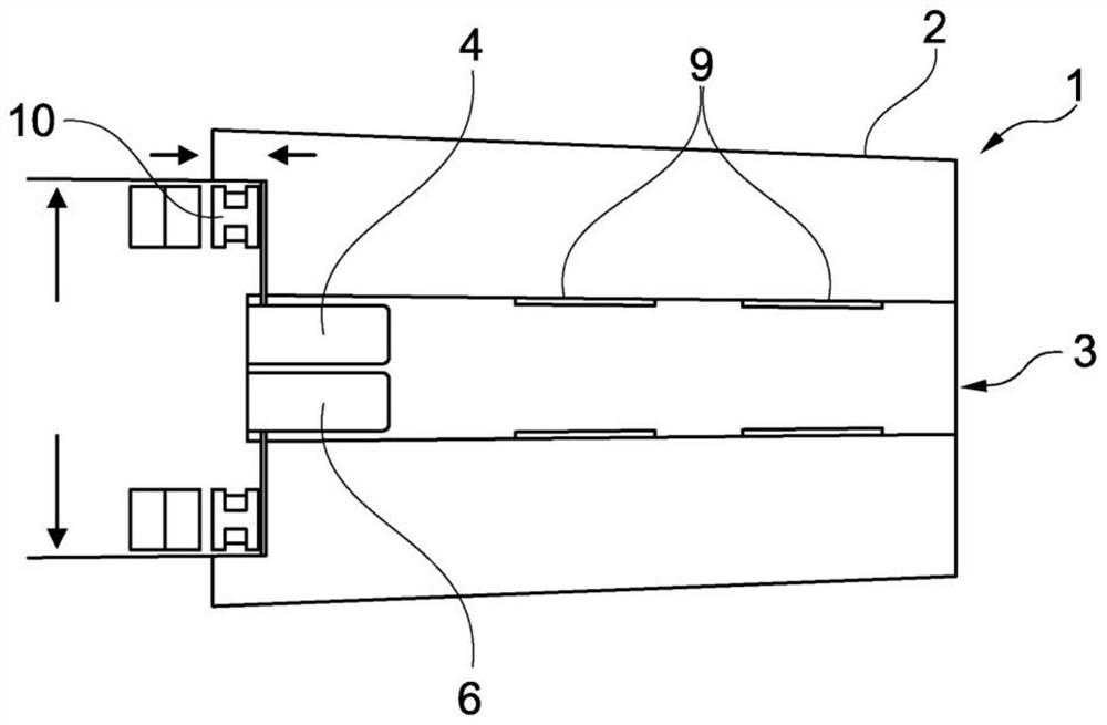
[0050] figure 1 A schematic perspective view of a rolling element 1 according to an exemplary embodiment of the invention is shown. Such a rolling body 1 is mounted in a rolling bearing and serves for the movable guidance of the first bearing ring 11 and the second bearing ring 12 to each other, in particular for the movable inner ring 12 arranged in the outer ring 11 of the anti-rotation arrangement. Movement guidance. In this case, usually a plurality of rolling bodies are arranged between the outer ring 11 and the inner ring 12 and roll on the running surfaces of the outer ring 11 and the inner ring 12 . These are so-called measuring rollers, ie rolling elements 1 which are provided and designed for load measurement in rolling bearings.

[0051] The rolling element 1 here comprises a cylindr...


PUM


Abstract

The invention proposes a rolling element (1) for use in a rolling-element bearing (100), comprising an outer shell (2) and a bore (3), the bore (3) being preferably provided along a centre axis of the rolling element (1), the rolling element (1) comprising at least one sensor (5) for load measurement, which is arranged in the bore (3), and a transfer module for transferring the data measured by the sensor (5), the rolling element having an energy source, the energy source being provided for providing the energy required for the operation of the sensor (5) and / or of the transfer module, characterised in that the sensor (5) is a sensor that performs inductive measurement. The invention further proposes a rolling-element bearing and a method for load measurement.

Description

Background technique [0001] On large rolling bearings, which are used, for example, in wind power plants, enormous forces act during operation. Therefore, it is desirable to be able to perform load measurement of rolling bearings. [0002] For this purpose, it is known, for example, from EP 0 637 734 B1 to measure the deformation of the rolling bodies by means of strain gauges arranged in the bores of the rolling bodies, wherein the forces acting on the rolling bearing can be deduced from the deformation of the rolling bodies, That is load. However, strain gauge strips and their corresponding fixtures, usually adhesive, are very prone to wear and aging, not least because they are often in contact with grease and / or other lubricants in rolling bearings and must be replaced regularly. Therefore, such a load measurement is only possible under laboratory conditions or for a short limited time, or is possible for a limited time. [0003] It is known from EP 1 849 013 B1 to arran...

Claims


Application Information

Patent Timeline
Patent Type & Authority Applications(China)
IPC IPC(8): G01M3/04F16C19/52F16C41/00
CPCF16C19/522F16C41/008F16C33/34F16C2300/14F16C2233/00F16C41/004G01M13/04
Inventor 贡特尔·埃尔费特贝恩德·吕内堡约尔格·罗尔曼曼弗雷德·雷曼
Owner THYSSENKRUPP ROTHE ERDE
Learn More