Position information processing method of ultrasonic puncture needle, ultrasonic equipment and storage medium

An information processing method and puncture needle technology, which are applied to puncture needles, trocars, etc., can solve the problems of difficult ultrasonic beams, poor imaging effect of ultrasonic puncture needles, and unsuitable non-linear probes, etc. Low complexity, real-time detection, and the effect of ensuring detection accuracy

Active Publication Date: 2021-06-29
QINGDAO HISENSE MEDICAL EQUIP
View PDF25 Cites 2 Cited by
  • Summary
  • Abstract
  • Description
  • Claims
  • Application Information

AI Technical Summary

Problems solved by technology

In the actual puncture process, because the surface of the ultrasonic puncture needle is very smooth, the ultrasonic wave is very easy to form a mirror reflection on the outer wall of the ultrasonic puncture needle. Therefore, when the angle between the ultrasonic puncture needle and the ultrasonic emission beam is smaller, the echo signal of the ultrasonic needle will The smaller the size, the worse the needle body imaging effect of the ultrasonic puncture needle
[0003] In related technologies, ultrasonic probes include linear array probes and non-linear array probes. Since linear array probes can easily control the angle of each array element’s emission beam, the deflection control method based on ultrasonic emission beams can make the needle body imaging effect of ultrasonic puncture needles Good, but not suitable for nonlinear array probes
Each array element of the nonlinear array probe has a different beam angle, and it is difficult to make the ultrasonic beam and the ultrasonic needle body appear perpendicular, so that the imaging effect of the ultrasonic puncture needle is better. Therefore, an ultrasonic puncture needle is needed. Position information processing method to solve the problem that the deflection control method for the angle of the transmitting beam in the related art is difficult to apply to the situation of the non-linear array probe

Method used


Image

  • Position information processing method of ultrasonic puncture needle, ultrasonic equipment and storage medium
  • Position information processing method of ultrasonic puncture needle, ultrasonic equipment and storage medium
  • Position information processing method of ultrasonic puncture needle, ultrasonic equipment and storage medium

Examples


Embodiment approach 1

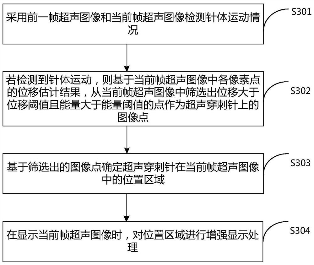
[0150] Perform displacement estimation on the previous frame of ultrasound image and the current frame of ultrasound image, obtain the displacement estimation result of each pixel in the current frame of ultrasound image, and determine the displacement average of each pixel displacement estimation result, if the displacement average is not greater than the first A preset threshold value, it is determined that the needle movement is detected, otherwise, it is determined that the needle movement is not detected.

[0151] Exemplarily, any one of a cross-correlation displacement estimation algorithm, a phase difference-based displacement estimation algorithm, and a zero-phase displacement estimation algorithm is used to perform displacement estimation on the previous frame of ultrasound image and the current frame of ultrasound image.

[0152] For example, using the cross-correlation displacement estimation algorithm to estimate the displacement of the previous frame of ultrasound ...

Embodiment approach 2

[0181] Determine the energy difference between the previous frame of ultrasound image and the current frame of ultrasound image, and determine the energy average of the absolute value of the energy difference of each pixel, if the energy average is not greater than the second preset threshold, then determine the detection If the needle movement is detected, otherwise, it is determined that no needle movement is detected.

[0182] Exemplarily, the energy value of each image point in the ultrasonic image of the previous frame and the ultrasonic image of the current frame can be calculated by the following energy formula (9):

[0183] Power=sqrt(I*I+Q*Q) (9)

[0184] Among them, Power represents the energy value of the image point, I is determined by the I part of the IQ data, Q is determined by the Q part of the IQ data, and the IQ data is determined by the ultrasonic image where it is located.

[0185] After determining the energy value of each image point in the ultrasonic im...

Embodiment approach 3

[0188] Perform displacement estimation on the previous frame of ultrasound image and the current frame of ultrasound image, obtain the displacement estimation result of each pixel in the current frame of ultrasound image, and determine the displacement average value of the displacement estimation result of each pixel;

[0189] Determine the energy difference between the previous frame of ultrasound image and the current frame of ultrasound image, and determine the energy average value of the absolute value of the energy difference of each pixel;

[0190]If the average displacement value is not greater than the first preset threshold and the average energy value is not greater than the second preset threshold, it is determined that the needle motion is detected; otherwise, it is determined that the needle motion is not detected.

[0191] For the specific implementation of the above steps, reference may be made to Embodiment 1 of the needle motion detection and Embodiment 2 of th...


PUM


Abstract

The invention relates to the technical field of ultrasonic data processing, and discloses a position information processing method of an ultrasonic puncture needle, ultrasonic equipment and a storage medium. The method comprises the following steps that a previous frame of ultrasonic image and a current frame of ultrasonic image are adopted to detect the movement condition of a needle body, and when the movement of the needle body is detected, on the basis of a displacement estimation result of each pixel point in the current frame of ultrasonic image, points with the displacement larger than a displacement threshold value and the energy larger than an energy threshold value are screened out from the current frame of ultrasonic image to serve as image points on the ultrasonic puncture needle, and then the position area of the ultrasonic puncture needle in the current frame of ultrasonic image is obtained. Therefore, the method for detecting the ultrasonic puncture needle, which is accurate in real time and can be applied to a linear probe and a non-linear probe, can be provided.

Description

technical field [0001] The present application relates to the technical field of ultrasonic data processing, and in particular to a method for processing position information of an ultrasonic puncture needle, an ultrasonic device, and a storage medium. Background technique [0002] During the operation of ultrasonic puncture, the internal structure of the tissue, the needle tip of the ultrasonic puncture needle and the needle body of the ultrasonic puncture needle can be seen by using the ultrasonic image. When performing ultrasonic puncture, it is not only necessary to accurately pierce the ultrasonic puncture needle to the site to be punctured, but also to avoid special parts such as nerve tissue. In the actual puncture process, because the surface of the ultrasonic puncture needle is very smooth, the ultrasonic wave is very easy to form a mirror reflection on the outer wall of the ultrasonic puncture needle. Therefore, when the angle between the ultrasonic puncture needle...

Claims


Application Information

Patent Timeline
Patent Type & Authority Applications(China)
IPC IPC(8): A61B17/34
CPCA61B17/3403A61B2017/3413
Inventor 付传卿陈永丽朱超超
Owner QINGDAO HISENSE MEDICAL EQUIP
Why Eureka
Try Eureka