

Novel water conservancy detection equipment
A detection equipment and water conservancy technology, which is applied in the field of new water conservancy detection equipment, can solve the problems of slowing down the filtration speed of liquid, increasing the time of water quality detection, and the liquid is easy to freeze, so as to achieve the effect of accelerating the speed and reducing the time of detection
- Summary
- Abstract
- Description
- Claims
- Application Information
AI Technical Summary
Problems solved by technology
Method used
Image

Examples
Embodiment 1
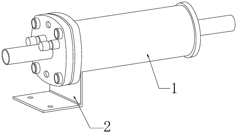
[0029] as attached figure 1 To attach Figure 6 Shown:
[0030] The present invention provides a new type of water conservancy testing equipment, the structure of which includes a filter cartridge 1 and a support seat 2, and the top end of the support seat 2 is welded and connected to the bottom surface of the left end of the filter cartridge 1.
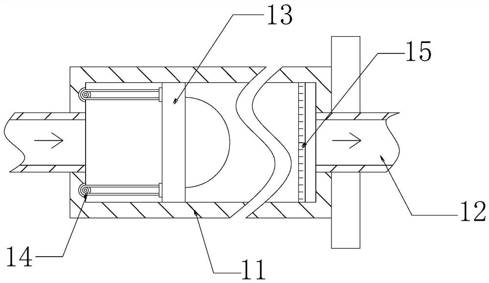
[0031] The filter cartridge 1 includes a cylinder body 11, a drain pipe 12, a push mechanism 13, a pull cord 14, and a filter screen 15. The drain pipe 12 is respectively installed in the middle of both ends of the cylinder body 11, and the push mechanism 13 is sleeved on the cylinder body. 11, the right end of the pull cord 14 is connected to the left side of the push mechanism 13 near the upper and lower ends, and the outer wall of the filter screen 15 is nested inside the right end of the cylinder 11.
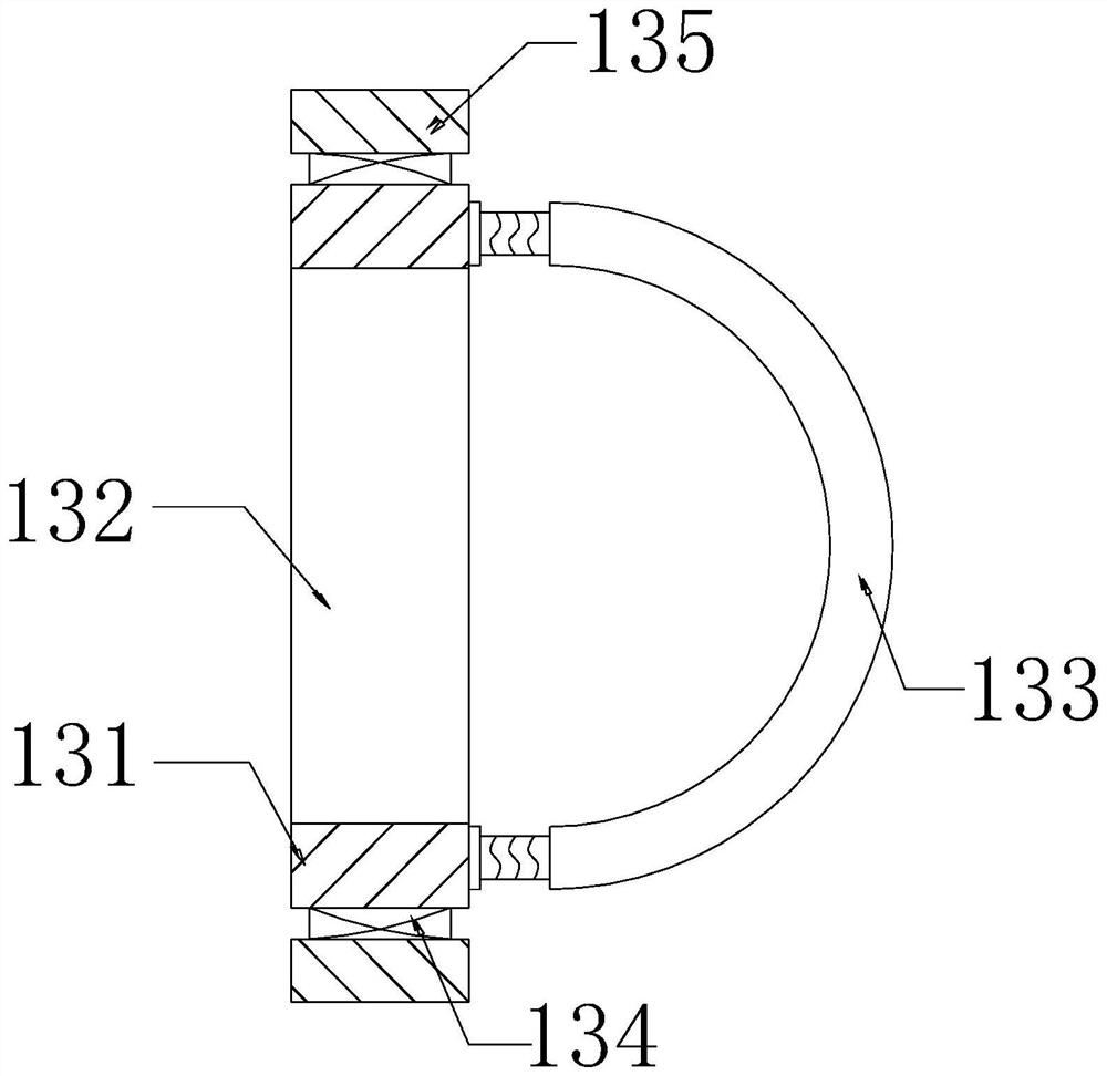
[0032] Wherein, the pushing mechanism 13 includes a force plate 131, an opening 132, a push plate 133, an elastic block 134, an...
Embodiment 2
[0039] as attached Figure 7 to attach Figure 8 Shown:
[0040] Wherein, the push block 135 includes a support block 35a, a clearing block 35b, an inner cavity 35c, a rebound block 35d, and a pushing ball 35e, the clearing block 35b is suspended in the middle of the supporting block 35a, and the inner cavity 35c is opened on the supporting block 35a Inside the middle and upper position, the rebound block 35d is set on the inner wall at both ends of the inner cavity 35c, the push ball 35e is movably matched with the rebound block 35d, and the left side of the support block 35a is provided with a groove near the bottom, which is beneficial for the liquid to flow along. Enter along the groove on the left side of the support block 35a, increase the pushing force received by the push block 135, and accelerate the moving speed of the push mechanism 13.
[0041] Wherein, the clearing block 35b includes a support rod b1, a push block b2, and a telescopic block b3, the top center of...
PUM
 Abstract
Description
Claims
Application Information