Unmanned aerial vehicle remote sensing device with good protection effect for surveying and mapping engineering measurement
A technology of engineering measurement and remote sensing of aircraft, which is applied to aircraft indicating devices, unmanned aerial vehicles, motor vehicles, etc., can solve problems such as damage to remote sensing devices, poor use effect, poor protection effect, etc., to ensure normal use and reduce vibration. , good protective effect
- Summary
- Abstract
- Description
- Claims
- Application Information
AI Technical Summary
Problems solved by technology
Method used
Image

Examples
Embodiment 1
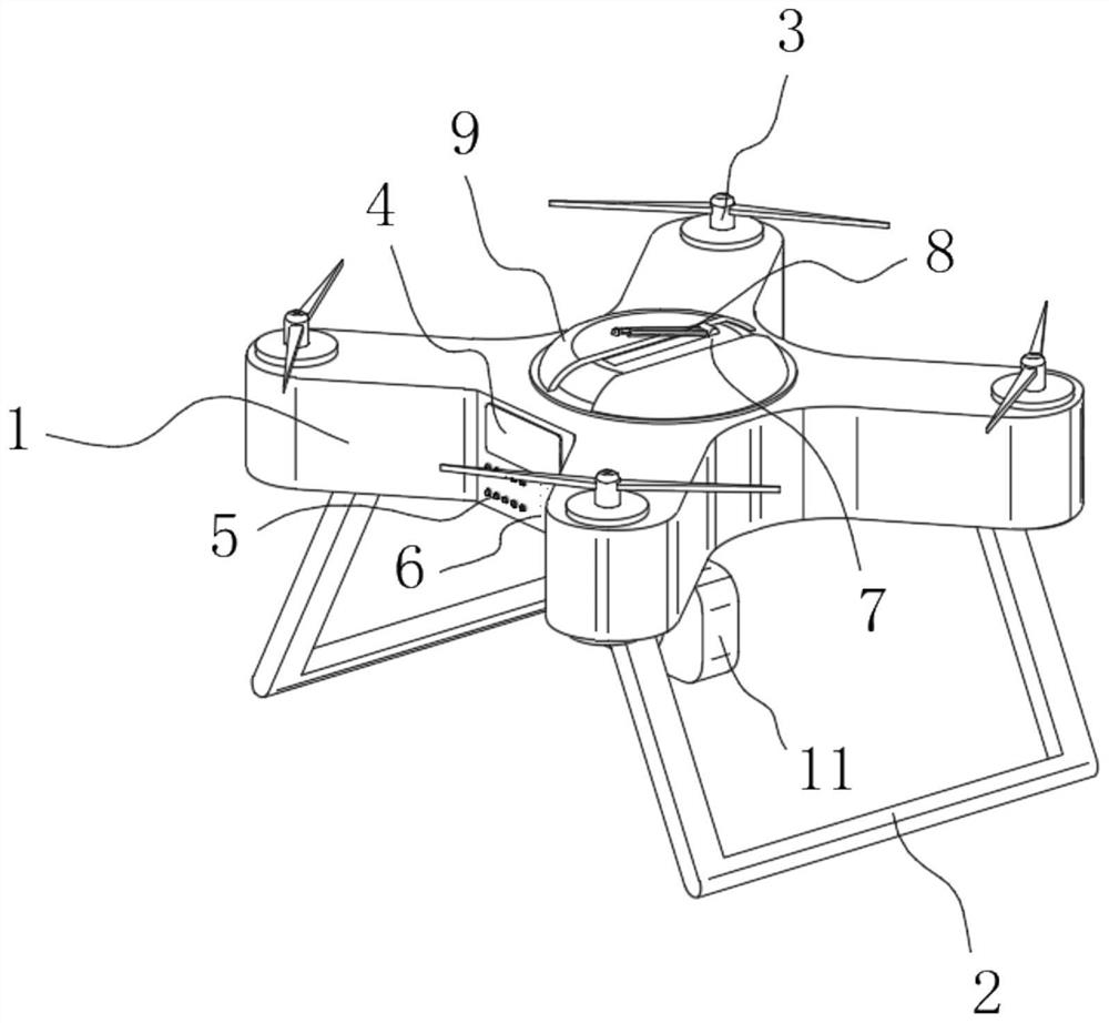
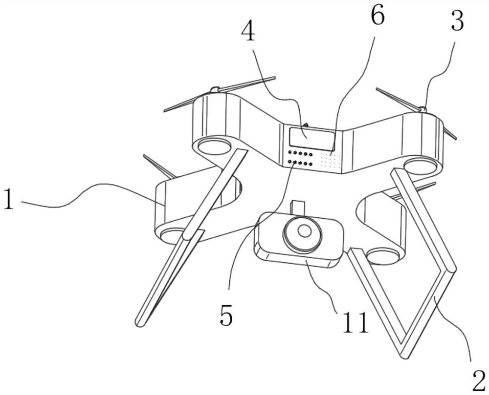
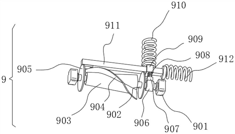
[0032] see Figure 1-8 , the present invention provides a technical solution: an unmanned aerial vehicle remote sensing device with good protective effect for surveying and mapping engineering survey, comprising a body 1, the bottom of the body 1 is fixedly connected with a support frame 2, and the top of the body 1 is rotatably connected with an organic paddle 3, The outer wall of the front end of the body 1 is fixedly connected with a display screen 4, the outer wall of the front end of the body 1 is fixedly connected with an indicator light 5 below the display screen 4, and the outer wall of the front end of the body 1 is fixedly connected with a speaker 6 on the right side of the indicator light 5, The body 1 is clamped with a remote sensing device main body 7 , the top of the remote sensing device main body 7 is hinged with an antenna 8 , and the top of the remote sensing device main body 7 is provided with a protective device 9 .
[0033]Protective device 9 comprises mov...
Embodiment 2
[0036] see Figure 1-8 As shown, on the basis of Embodiment 1, the present invention provides a technical solution: the inner wall of the body 1 is fixedly connected with a rubber pad 12, the inside of the body 1 is provided with a concave groove 13, and the inner wall of one side of the concave groove 13 is fixedly connected with a Back-moving spring 14, back-moving spring 14 is fixedly connected with slide plate 15 away from the side of concave groove 13, and slide plate 15 is fixedly connected with wedge-shaped block 16 away from the side of back-moving spring 14, and the top of wedge-shaped block 16 is fixedly connected with elastic block 17, The top of the elastic block 17 is fixedly connected with a trapezoidal block 18, and one side outer wall of the remote sensing device main body 7 is provided with a wedge-shaped draw-in groove 19, and one side inner wall of the wedge-shaped draw-in groove 19 is fixedly connected with the outer wall of the wedge-shaped block 16, and th...
Embodiment 3
[0039] see Figure 1-8 As shown, on the basis of Embodiment 1 and Embodiment 2, the present invention provides a technical solution: the outer wall of the bottom of the body 1 is fixedly connected with a hinged rod 10, the bottom of the hinged rod 10 is hinged with a camera 11, and the inside of the hinged rod 10 Open a square hole 20, the side of the camera 11 close to the hinge rod 10 is fixedly connected with a hinged support 21, the side of the hinged support 21 away from the camera 11 is hinged with a telescopic cylinder 22, the top of the telescopic cylinder 22 is connected to the bottom outer wall of the body 1 Hinged, the hinged support 21 runs through the inside of the square hole 20, the size of the square hole 20 matches the size of the telescopic cylinder 22, and the output end of the camera 11 is electrically connected to the UAV sensor, the surveying and mapping module, and the wireless data transmission module in turn , an information processing unit, an informa...
PUM
 Abstract
Description
Claims
Application Information
 - R&D
- Intellectual Property
- Life Sciences
- Materials
- Tech Scout
- Unparalleled Data Quality
- Higher Quality Content
- 60% Fewer Hallucinations
Browse by: Latest US Patents, China's latest patents, Technical Efficacy Thesaurus, Application Domain, Technology Topic, Popular Technical Reports.
© 2025 PatSnap. All rights reserved.Legal|Privacy policy|Modern Slavery Act Transparency Statement|Sitemap|About US| Contact US: help@patsnap.com