Pure electric loader
A loader, pure electric technology, applied in the direction of earth mover/shovel, construction, etc., can solve the problems that cannot meet the display requirements of pure electric construction machinery, incomplete function parameters, etc.
- Summary
- Abstract
- Description
- Claims
- Application Information
AI Technical Summary
Problems solved by technology
Method used
Image
Examples
Embodiment 1
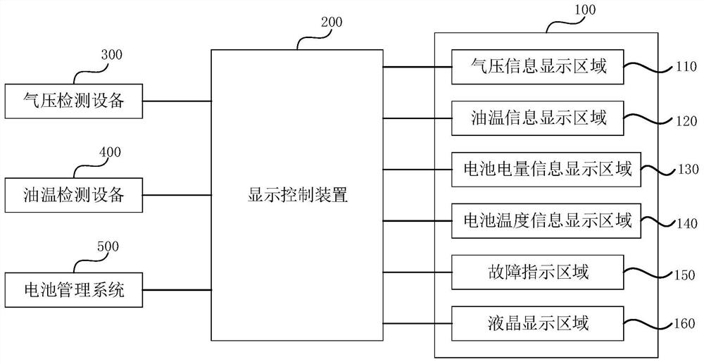
[0028] figure 1 It is a system structure diagram of a pure electric loader provided in Embodiment 1 of the present invention. refer to figure 1 , the pure electric loader includes: a display device 100, a display control device 200, an air pressure detection device 300, an oil temperature detection device 400 and a battery management system 500;
[0029] The display device 100, the air pressure detection device 300, the oil temperature detection device 400 and the battery management system 500 are all electrically connected to the display control device 200; wherein, the display device 100 includes an air pressure information display area 110, an oil temperature information display area 120, battery power information Display area 130, battery temperature information display area 140, fault indication area 150 and liquid crystal display area 160; air pressure detection device 300 is used to collect the air pressure information of the air storage tank; oil temperature detection...
Embodiment 2
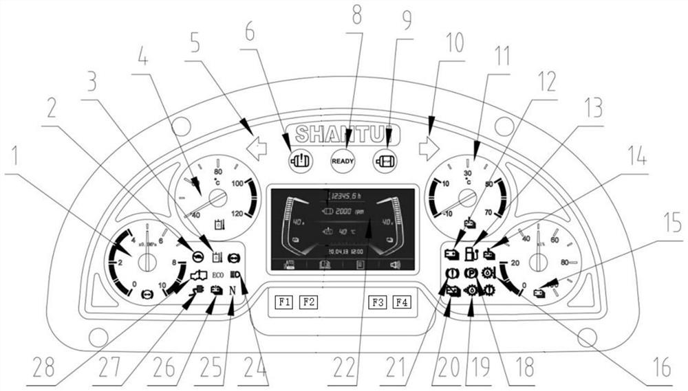
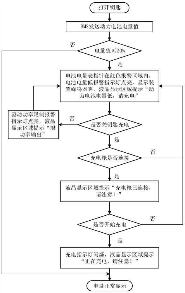
[0040] figure 2 It is a display system interface diagram of a pure electric loader provided in Embodiment 2 of the present invention, image 3 It is the battery power display control flow chart provided in the second embodiment of the present invention, Figure 4 It is the battery temperature display control flow chart provided in the second embodiment of the present invention, Figure 5 It is the air pressure information display control flow chart provided in the second embodiment of the present invention, Figure 6 It is the flow chart of the fault display control of the whole machine system provided in the second embodiment of the present invention, Figure 7 It is the main menu control flow chart provided in Embodiment 2 of the present invention.
[0041] refer to figure 2 , the display system interface includes: brake air pressure gauge 1, drive power limit alarm indicator 2, high working oil temperature alarm indicator 3, working oil temperature gauge 4, left turn ...
PUM
 Abstract
Description
Claims
Application Information
 - R&D
- Intellectual Property
- Life Sciences
- Materials
- Tech Scout
- Unparalleled Data Quality
- Higher Quality Content
- 60% Fewer Hallucinations
Browse by: Latest US Patents, China's latest patents, Technical Efficacy Thesaurus, Application Domain, Technology Topic, Popular Technical Reports.
© 2025 PatSnap. All rights reserved.Legal|Privacy policy|Modern Slavery Act Transparency Statement|Sitemap|About US| Contact US: help@patsnap.com


