Concrete string barrel structure and concrete-filled steel tube pouring construction method

A technology of concrete and string barrels, which is applied in the direction of special structures, buildings, building components, etc., can solve the problems of increasing the pouring height of steel pipe concrete, difficulty in pouring concrete for outer steel frame concrete steel pipe columns, and concrete segregation, so as to solve the problem of steel pipe concrete pouring puzzle effect

Active Publication Date: 2021-06-29
CHINA MCC17 GRP
View PDF6 Cites 2 Cited by
  • Summary
  • Abstract
  • Description
  • Claims
  • Application Information

AI Technical Summary

Problems solved by technology

[0006] Aiming at the deficiencies of the prior art, the present invention provides a concrete string barrel structure and a construction method for concrete-filled steel pipe pouring, which solves the problem that concrete pouring is often carried out by a distributing machine. The radius is fixed, but due to the height difference between the core tube and the outer frame, it is difficult to pour the concrete of the outer steel frame concrete column. Columns and other components often have two or three floors and one section, which increases the pouring height of the steel tube concrete itself, and the concrete is prone to segregation.

Method used


Image

  • Concrete string barrel structure and concrete-filled steel tube pouring construction method
  • Concrete string barrel structure and concrete-filled steel tube pouring construction method
  • Concrete string barrel structure and concrete-filled steel tube pouring construction method

Examples


Embodiment Construction

[0025] The following will clearly and completely describe the technical solutions in the embodiments of the present invention with reference to the accompanying drawings in the embodiments of the present invention. Obviously, the described embodiments are only some, not all, embodiments of the present invention. Based on the embodiments of the present invention, all other embodiments obtained by persons of ordinary skill in the art without making creative efforts belong to the protection scope of the present invention.

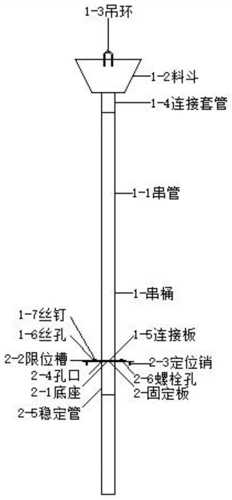
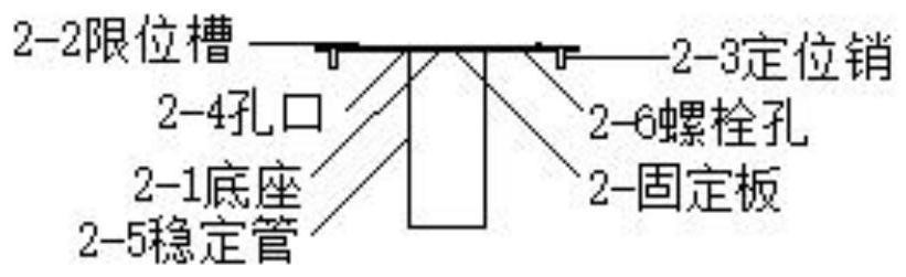
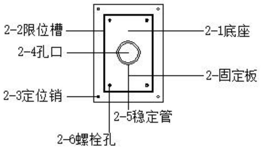
[0026] see Figure 1-4 , the present invention provides a technical solution: a concrete string barrel structure, including string barrels and fixing plates, string barrels and fixing plates are connected by screws, and string barrels are composed of string pipes, hoppers, lifting rings, connecting sleeves, connecting plates, Composed of wire holes and screw nails, the bottom of the hopper is equipped with a connecting sleeve, the upper part is connected with ...


PUM


Abstract

The invention discloses a concrete string barrel structure and a concrete-filled steel tube pouring construction method, and relates to the technical field of steel-concrete structures. The concrete string barrel structure comprises a string barrel and a fixing plate, wherein the string barrel and the fixing plate are connected through screws; the string barrel consists of a string tube, a hopper, a lifting ring, a connecting sleeve, a connecting plate, screw holes and screws; the connecting sleeve is arranged at the bottom of the hopper; the upper part of the hopper is connected with the lifting ring; the connecting plate is arranged on the periphery of the string tube; and a plurality of screw holes are symmetrically formed in the connecting plate. According to the concrete string barrel structure and the concrete-filled steel tube pouring construction method, through the improvement of the construction method and the concrete string barrel structure, the asynchronous construction of a steel frame-reinforced concrete core tube structure and high-quality concrete-filled steel tube pouring are realized, and the problem of concrete-filled steel tube pouring caused by the height difference between the core tube and an outer frame and the height of the steel tube is solved.

Description

technical field [0001] The invention relates to the technical field of steel-concrete structures, in particular to a concrete string barrel structure and a construction method for pouring steel pipe concrete. Background technique [0002] With the development of the construction industry, the steel-concrete structure system has the advantages of both steel structure and concrete structure, and has low cost, good economy, and fast construction speed. Steel-concrete structure has gradually become the main structural form of high-rise buildings, especially super high-rise buildings. . [0003] Among steel-concrete structures, steel-filled steel tube concrete is widely used due to its advantages of high bearing capacity, good ductility, superior seismic performance, fire resistance and corrosion resistance. According to the characteristics of steel-concrete structures, the core tube concrete structure is generally ahead of the outer steel frame construction, and concrete pouring...

Claims


Application Information

Patent Timeline
Patent Type & Authority Applications(China)
IPC IPC(8): E04B1/30E04G21/02E04B1/34
CPCE04B1/30E04B1/34E04G21/02
Inventor 乔小明
Owner CHINA MCC17 GRP
Why Eureka
Try Eureka