
Control method of electric control pressure release valve in diesel engine fuel system

A fuel system and control method technology, applied in electrical control, engine control, fuel injection control, etc., can solve the problems that static non-leakage injectors cannot release pressure proportional flow valves and electronically controlled pressure relief valves, etc. The effect of poor pressure followability

Pending Publication Date: 2021-06-29
WUXI WEIFU HIGH TECH CO LTD
View PDF12 Cites 4 Cited by
  • Summary
  • Abstract
  • Description
  • Claims
  • Application Information

AI Technical Summary

Problems solved by technology

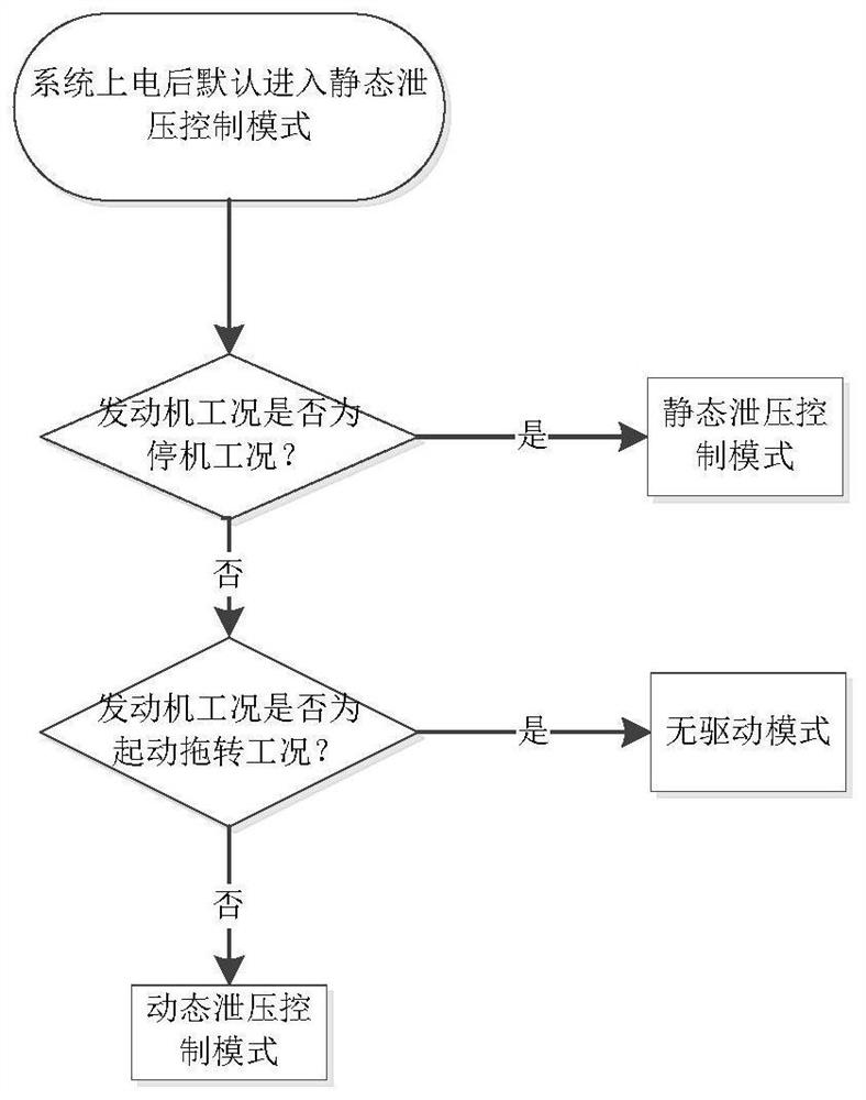
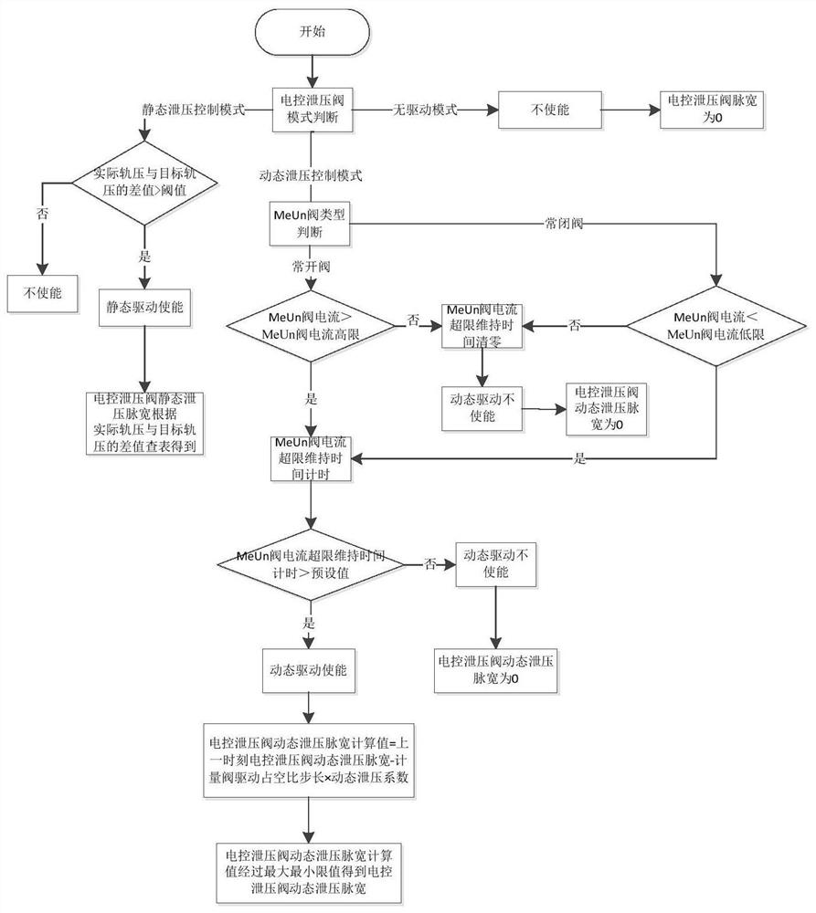
[0004] The invention provides a control method for an electronically controlled pressure relief valve in a diesel engine fuel system, which solves the problems in the related art that the static non-leakage injector cannot release pressure, and how to coordinate the proportional flow valve and the electronically controlled pressure relief valve to control the rail pressure The problem

Method used


Image

  • Control method of electric control pressure release valve in diesel engine fuel system
  • Control method of electric control pressure release valve in diesel engine fuel system
  • Control method of electric control pressure release valve in diesel engine fuel system

Examples


Embodiment Construction

[0040] It should be noted that, in the case of no conflict, the embodiments of the present invention and the features in the embodiments can be combined with each other. The present invention will be described in detail below with reference to the accompanying drawings and examples.

[0041] In order to enable those skilled in the art to better understand the solutions of the present invention, the technical solutions in the embodiments of the present invention will be clearly and completely described below in conjunction with the drawings in the embodiments of the present invention. Obviously, the described embodiments are only Embodiments of some, but not all, embodiments of the present invention. Based on the embodiments of the present invention, all other embodiments obtained by persons of ordinary skill in the art without creative efforts shall fall within the protection scope of the present invention.

[0042] It should be noted that the terms "first" and "second" in th...


PUM


Abstract

The invention relates to the technical field of diesel injection system control, and particularly discloses a control method of an electric control pressure release valve in a diesel engine fuel system. A rail pressure control structure of the diesel engine fuel system comprises an electric control unit, an oil pump, an oil rail, a proportional flow valve, the electric control pressure release valve and a rail pressure sensor, wherein the oil pump is connected to the oil rail, the proportional flow valve is arranged on the oil pump, the electric control pressure release valve and the rail pressure sensor are both arranged on an oil rail, the proportional flow valve, the electric control pressure release valve and the rail pressure sensor are all electrically connected to the electric control unit, the control method of the electric control pressure release valve in the diesel engine fuel system comprises the following steps that a current working condition of an engine is obtained; and the electric control pressure release valve is correspondingly controlled according to different states of the current working condition of the engine. According to the control method of the electric control pressure release valve in the diesel engine fuel system, the defects that a leakage-free fuel injector is poor in rail pressure following performance under the working condition of reversed towing of an engine, and pressure cannot be released during shutdown are overcome.

Description

technical field [0001] The invention relates to the technical field of diesel injection system control, in particular to a control method for an electronically controlled pressure relief valve in a diesel engine fuel system. Background technique [0002] At present, fuel systems equipped with static non-leakage injectors rely solely on proportional flow valves to achieve rail pressure control. The proportional flow valve leaks and cannot be completely closed, and the existence of the high-level fuel tank prevents the oil pump from completely stopping the oil intake. These two aspects cause the high pressure in the high-pressure fuel rail to remain high after the engine stops, and the rail pressure is too high when restarting. Excessive rail pressure will cause a certain impact on the components, causing the safety valve to be flushed open, causing difficulty in starting and affecting the service life of the components. [0003] If the injector is used for air-injection pres...

Claims


Application Information

Patent Timeline
IPC IPC(8): F02D41/38
CPCF02D41/3863Y02T10/40
Inventor 王亚伟杨文燕孙明超
Owner WUXI WEIFU HIGH TECH CO LTD
Learn More