Electric furnace

A technology of electric furnace and furnace body, applied in the field of electric furnace, which can solve the problems of reducing the service life of electric furnace, easy deformation and failure of furnace shell, and achieve the effect of avoiding deformation

Pending Publication Date: 2021-06-29
CHINA ENFI ENGINEERING CORPORATION
View PDF6 Cites 2 Cited by
  • Summary
  • Abstract
  • Description
  • Claims
  • Application Information

AI Technical Summary

Problems solved by technology

However, in the related art, due to factors such as difficult design or unreasonable setting of expansion joints, melt pouring into expansion joints during smelting production, etc., the lining brick layer still generates a large expansion force, and the furnace shell expands the lining brick layer. It is easy to deform and fail under the action of force, which reduces the service life of the electric furnace

Method used


Image

  • Electric furnace
  • Electric furnace
  • Electric furnace

Examples


Embodiment Construction

[0034] Embodiments of the invention are described in detail below, examples of which are illustrated in the accompanying drawings. The embodiments described below by referring to the figures are exemplary and are intended to explain the present invention and should not be construed as limiting the present invention.

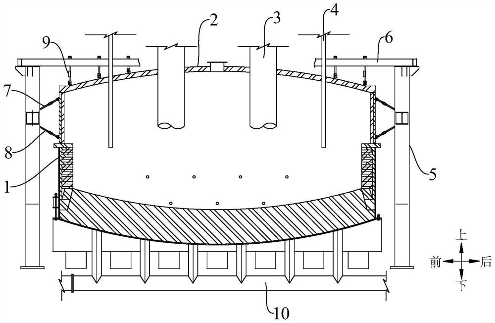
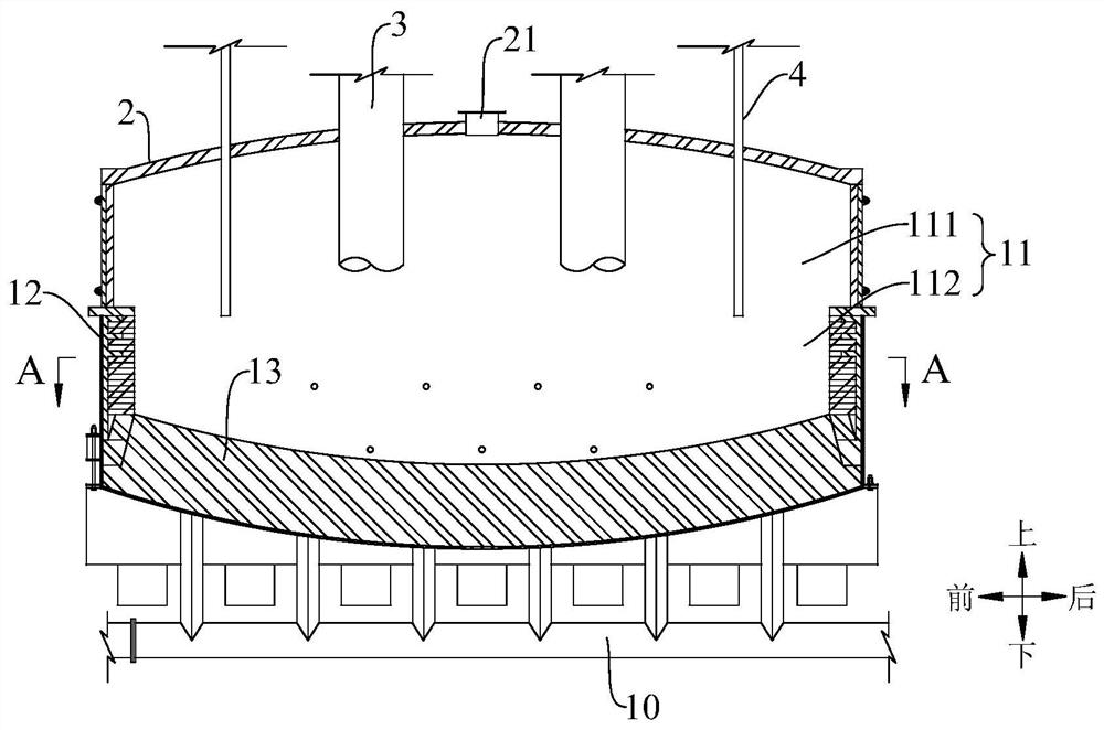
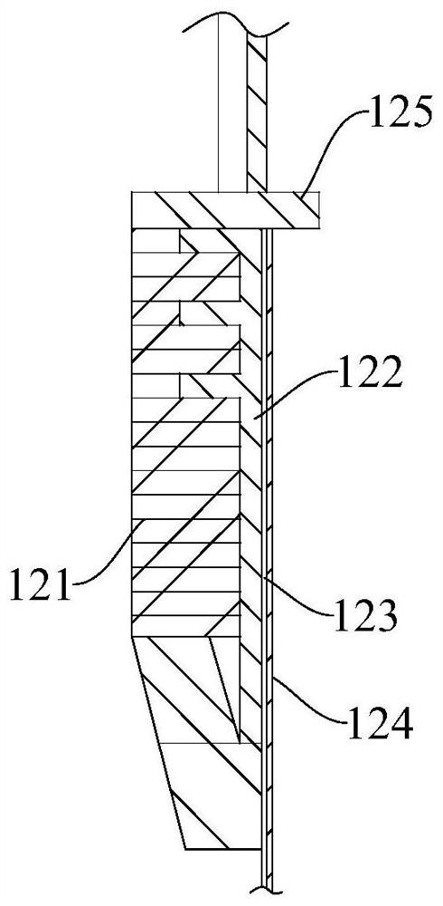
[0035] Such as Figure 1 to Figure 7 As shown, the electric furnace according to the embodiment of the present invention includes a furnace body 1, which has a furnace chamber 11, the furnace chamber 11 includes an upper chamber 111 and a molten pool 112 below the upper chamber 111, and the furnace body 1 includes a bottom wall 13 and the peripheral wall 12, the cross section of the peripheral wall 12 is circular, the peripheral wall 12 of the molten pool 112 includes a lining brick layer 121 and a furnace shell 124 positioned outside the lining brick layer 121, the furnace shell 124 includes a plurality of shell segments 1241, The bottom ends of the multiple sh...


PUM


Abstract

The invention discloses an electric furnace. The electric furnace comprises a furnace body, wherein a furnace chamber is formed in the furnace body; the furnace chamber comprises an upper chamber and a molten pool positioned below the upper chamber; the furnace body comprises a bottom wall and a peripheral wall; the cross section of the peripheral wall is circular; the peripheral wall of the molten pool comprises a lining brick layer and a furnace shell positioned on the outer side of the lining brick layer; the furnace shell comprises a plurality of shell sections; the bottom ends of the shell sections are connected with the bottom wall; the shell sections are arranged in sequence along the circumferential direction of the peripheral wall; and the end parts of two adjacent shell sections are connected through an expansion regulator. The furnace shell of the electric furnace can keep a hooping effect on the lining brick layer, and can be adaptively regulated along with the expansion effect of the lining brick layer, so that deformation and failure of the furnace shell are avoided.

Description

technical field [0001] The invention relates to the technical field of smelting equipment, in particular to an electric furnace. Background technique [0002] For example, the furnace wall of an electric furnace used for non-ferrous metal smelting includes a lining brick layer and a furnace shell arranged sequentially from the inside to the outside. In order to reduce the influence of thermal expansion of the lining brick layer, reasonable expansion joints are usually reserved between the lining bricks. However, in the related art, due to factors such as difficult design or unreasonable setting of expansion joints, melt pouring into expansion joints during smelting production, etc., the lining brick layer still generates a large expansion force, and the furnace shell expands the lining brick layer. It is easy to deform and fail under the action of force, which reduces the service life of the electric furnace. Contents of the invention [0003] The present invention aims t...

Claims


Application Information

Patent Timeline
Patent Type & Authority Applications(China)
IPC IPC(8): F27B14/06F27B14/08F27D1/04F27D1/00
CPCF27B14/06F27B14/08F27D1/04F27D1/0026F27D1/0043F27B2014/0843
Inventor 许欣陆金忠李海春曹珂菲刘恺李晓霞
Owner CHINA ENFI ENGINEERING CORPORATION
Why Eureka
Try Eureka