
Method for realizing high-frequency phase demodulation in distributed optical fiber sensing system

A distributed optical fiber and phase demodulation technology, which is applied in measuring devices, instruments, and measuring ultrasonic/sonic/infrasonic waves, etc., can solve the problems that the direct detection optical fiber distributed sensing system cannot detect the phase and cannot realize high-frequency detection. , to achieve the effect of improving the effective sampling rate, increasing the detection bandwidth, and reducing the data storage space

Pending Publication Date: 2021-06-29
NAT UNIV OF DEFENSE TECH
View PDF12 Cites 8 Cited by
  • Summary
  • Abstract
  • Description
  • Claims
  • Application Information

AI Technical Summary

Problems solved by technology

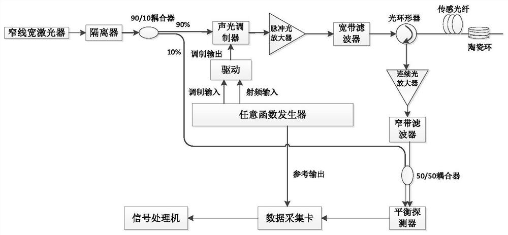
[0007] Aiming at the technical problems existing in the prior art, the present invention provides a method for realizing high-frequency phase demodulation in a distributed optical fiber sensing system, which solves the problem that the direct detection type optical fiber distributed sensing system cannot detect the phase and the traditional uniform sampling Limited by the disadvantage that Nyquist sampling theorem cannot realize high-frequency detection, the combination of heterodyne phase demodulation and compressed sensing realizes high-frequency phase demodulation of vibration signals

Method used


Image

  • Method for realizing high-frequency phase demodulation in distributed optical fiber sensing system
  • Method for realizing high-frequency phase demodulation in distributed optical fiber sensing system
  • Method for realizing high-frequency phase demodulation in distributed optical fiber sensing system

Examples


Embodiment Construction

[0057] The present invention will be further described below in conjunction with the accompanying drawings and specific preferred embodiments, but the protection scope of the present invention is not limited thereby.

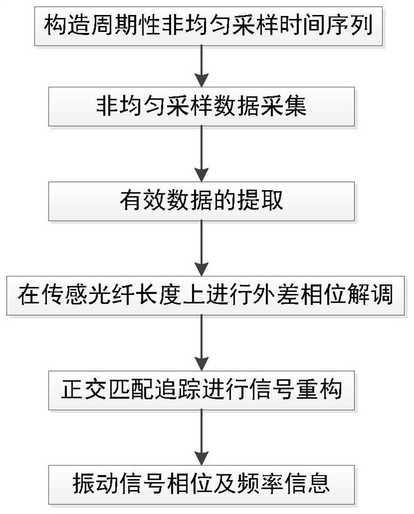
[0058] Such as figure 1 As shown, a method for realizing all-fiber high-frequency phase demodulation in a distributed optical fiber sensing system based on periodic non-uniform sampling includes the following steps:

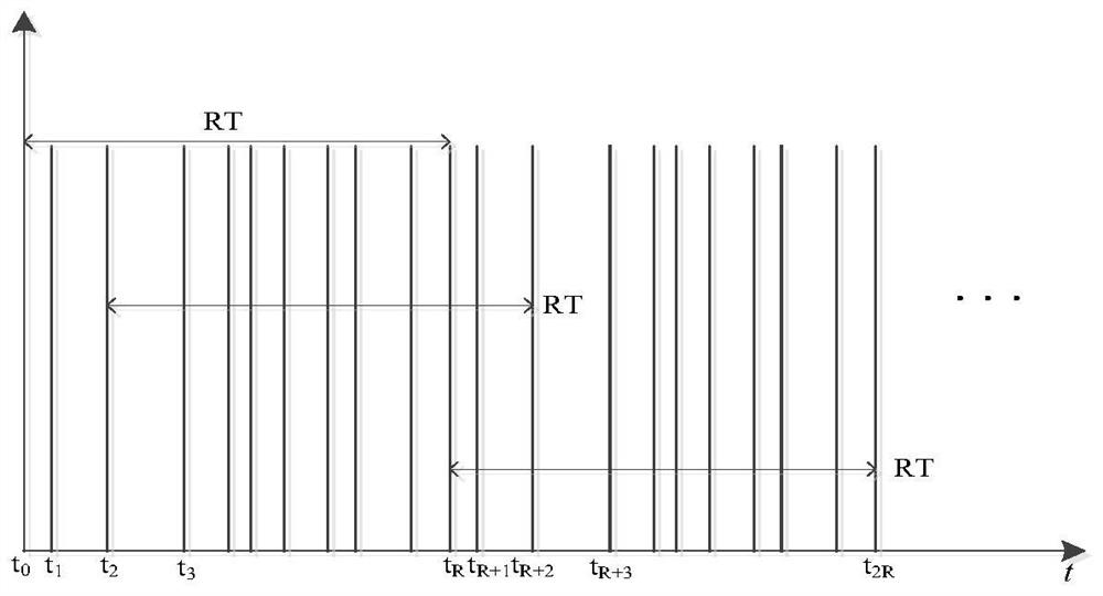
[0059] S1. Construct a periodic non-uniform sampling time series;

[0060] S2. Using the periodic non-uniform sampling time series constructed by S1 to generate a periodic non-uniform sampling pulsed light sequence to collect the original data;

[0061] S3. Design the matrix to extract valid data from the raw data collected in S2;

[0062] S4. Perform heterodyne phase demodulation on the data extracted by S3 over the length of the sensing fiber;

[0063] S5. Using the quadrature matching pursuit algorithm to reconstruct the signal of the heterod...


PUM


Abstract

The invention belongs to the technical field of optical fiber distributed sensing, and relates to a method for realizing high-frequency phase demodulation in a distributed optical fiber sensing system. The method mainly comprises the following steps of: S1, constructing a periodic non-uniform sampling time sequence; S2, generating a periodic non-uniform sampling pulse light sequence, and performing data acquisition on original data; S3, extracting effective data from the original data; S4, carrying out heterodyne phase demodulation on the length of the sensing optical fiber; S5, performing signal reconstruction on a heterodyne phase demodulation result by using an orthogonal matching pursuit algorithm; and S6, performing Fourier transform on the phase signal obtained by reconstruction to obtain the phase and frequency information of the vibration signal. According to the method, limitation of the Nyquist sampling theorem on the detection frequency band range of the distributed sensing system is broken through, the contradiction between long-distance sensing and high-frequency detection is solved under the condition that the hardware complexity does not need to be increased, recovery of the high-frequency phase signal is realized, and the recognition and classification of the vibration signal are facilitated.

Description

technical field [0001] The invention belongs to the technical field of optical fiber distributed sensing, and in particular relates to a method for realizing high-frequency phase demodulation in a distributed optical fiber sensing system. Background technique [0002] Phase-sensitive optical time domain reflectometer (Φ-OTDR) is a fiber optic distributed vibration and sound detection technology that has received widespread attention in recent years. It is used in health monitoring of large engineering structures, underwater acoustic detection, perimeter security of security systems and The application demands in fields such as resource exploration in the petroleum field are increasing day by day. The distributed structure of Φ-OTDR only needs one optical fiber to realize distributed sensing of vibration events. When external vibration acts on a certain position of the optical fiber, the length or refractive index of the optical fiber at this position changes, which in turn l...

Claims


Application Information

Patent Timeline
Patent Type & Authority Applications(China)
IPC IPC(8): G01H9/00
CPCG01H9/004
Inventor 孟洲余志杰路阳胡晓阳王建飞陈默陈伟陈羽朱琪
Owner NAT UNIV OF DEFENSE TECH
Learn More