Novel thermocouple device

A thermocouple, a new type of technology, applied in the direction of using electrical devices, measuring devices, measuring heat, etc., can solve problems such as the influence of wire life, messy wires, and increased labor burden, so as to improve the protection of fences, increase service life, and reduce The effect of artificial burden

Inactive Publication Date: 2021-06-29
江苏中致显科技有限公司
View PDF0 Cites 0 Cited by
  • Summary
  • Abstract
  • Description
  • Claims
  • Application Information

AI Technical Summary

Problems solved by technology

[0002] Thermocouple (thermocouple) is a commonly used temperature measuring element in temperature measuring instruments. It is usually composed of main parts such as thermal electrodes, insulating sleeve protection tubes and junction boxes. Thermocouple temperature measuring components usually require display instruments and recording instruments It is very inconvenient to carry and transfer the equipment as a whole, which requires a lot of labor and increases the labor burden; the existing thermocouple temperature measurement components are usually hand-held to achieve air temperature measurement or fixed temperature measurement in the area. , the results that can be detected by fixed temperature measurement are inaccurate. When handheld temperature measurement is performed, the air temperature in the area may be too high, and there may be harmful substances in the air, which will cause discomfort to the worker's body; thermocouple temperature measurement elements and display Meters, recording instruments and electronic regulators are usually connected by wires. The messy placement of wires and long-term external placement when not in use will affect the service life of the wires themselves; when the temperature detector is measuring temperature, the air flow The fluidity will directly affect the temperature measurement efficiency, so now a new type of thermocouple device is needed

Method used


Image

  • Novel thermocouple device
  • Novel thermocouple device
  • Novel thermocouple device

Examples


Embodiment 1

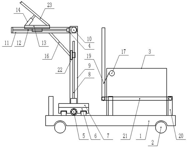
[0013] Embodiment 1: see figure 1 , figure 2 , image 3 , a new type of thermocouple device provided by the present invention is now described, including the base 1 and the electrically controlled travel wheels 2 provided at the four corners of the bottom of the base 1, and the upper end of one side of the base 1 in the length direction is provided with a cabinet 3 , the upper end of the other side of the length direction of the base 1 is provided with a temperature measuring mechanism 4, and the temperature measuring mechanism 4 is composed of a first screw rod 5 and a first wire rod provided on the upper end of the base 1 and along its width direction. The sliding base 6 provided directly above the position of the rod 5, the supporting base 7 provided at the upper end of the sliding base 6, the middle part of the upper end of the supporting base 7 and the second screw 8 provided along the vertical direction, the upper end of the supporting base 7 and along the The vertica...

Embodiment 2

[0014] Example 2: see figure 1 , figure 2 , a new type of thermocouple device provided by the present invention will now be described, the electrically controlled travel wheel 2 realizes electric control, the first screw rod 5 is along both sides of the length direction of the machine base 1, and the second screw rod 8 Guide rails are arranged in parallel at intervals along both sides of the machine base 1 in the width direction and on both sides of the third screw rod 12 along the width direction of the inner end of the frame 11, and between the vertical frames 9 The horizontal moving frame 22, the sliding base 6, the horizontal moving frame 22 and the side end of the moving base 13 are provided with connectors respectively between the corresponding screw mandrels, and the connecting parts include moving nuts that are sleeved on the screw rods And the bearing that is sheathed on the outside of the moving nut, the sliding base 6, the horizontal moving frame 22 and the moving...

Embodiment 3

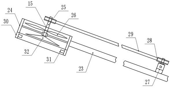
[0015] Embodiment 3: see figure 1 , figure 2, a new type of thermocouple device provided by the present invention is now described, the upper ends of the two sides of the mobile base 13 in the length direction are respectively hinged with a cylinder 14 and a swing rod 23, and the end of the piston rod in the cylinder 14 is connected to the swing rod 23 is externally hinged, the non-hinged end of the swing rod 23 is fixed with a first ring frame 24, and the middle part of the inner end of the first ring frame 24 is movable through a transmission shaft 25, and the upper side of the hinge end of the swing rod 23 is provided with A rotating motor 27, the output shaft of the rotating motor 27 and the upper end of the transmission shaft 25 are respectively covered with pulleys 28, and a belt 29 is set between the outside of the pulleys 28, and the outer equal arcs of the lower end of the transmission shaft 25 are evenly arranged. There are fan blades 26, the lower end of the trans...


PUM


Abstract

A novel thermocouple device disclosed by the invention comprises a machine base and electric control walking wheels. The upper end of the machine base is provided with a machine box and a temperature measurement mechanism, and the temperature measurement mechanism is composed of a first screw rod, a sliding base, a supporting base, a second screw rod, a vertical frame, a cross beam, a frame-shaped frame, a third screw rod, a movable base, an air cylinder, an electric control temperature measurement assembly and a supporting connecting rod. A movable shaft is arranged at the top end in the machine box, the two sides of the movable shaft in the length direction are provided with torsional springs respectively, a wire is wound around the middle of the movable shaft in the length direction, vertical rods are fixedly arranged at the upper ends of the two sides of the machine base in the width direction respectively, push rods are connected to the tops of the vertical rods, and push handle frames are arranged at the non-connecting ends of the push rods.

Description

technical field [0001] The invention relates to the field of thermocouples, in particular to a novel thermocouple device. Background technique [0002] Thermocouple (thermocouple) is a commonly used temperature measuring element in temperature measuring instruments. It is usually composed of main parts such as thermal electrodes, insulating sleeve protection tubes and junction boxes. Thermocouple temperature measuring components usually require display instruments and recording instruments It is very inconvenient to carry and transfer the equipment as a whole, which requires a lot of labor and increases the labor burden; the existing thermocouple temperature measurement components are usually hand-held to achieve air temperature measurement or fixed temperature measurement in the area. , the results that can be detected by fixed temperature measurement are inaccurate. When handheld temperature measurement is performed, the air temperature in the area may be too high, and the...

Claims


Application Information

Patent Timeline
Patent Type & Authority Applications(China)
IPC IPC(8): G01K7/02G01K1/00G01K1/14
CPCG01K1/00G01K1/146G01K7/02
Inventor 赵圣铭
Owner 江苏中致显科技有限公司
Why Eureka
Try Eureka