Liquefaction site pile foundation composite stress mechanism simulation device and test method thereof

A technology of liquefaction site and simulation device, which is applied in the field of geotechnical earthquake engineering, and can solve problems such as the inability to simulate the composite stress state of pile foundations

Inactive Publication Date: 2021-06-29
HARBIN INST OF TECH
View PDF9 Cites 1 Cited by
  • Summary
  • Abstract
  • Description
  • Claims
  • Application Information

AI Technical Summary

Problems solved by technology

[0003] The first object of the present invention is to provide a simulation device for the composite stress mechanism of pile foundations in liquefaction sites, so as to solve the problem that existing test devices cannot simulate the composite stress state of pile foundations when saturated soil liquefaction occurs when large lateral deformation occurs
[0004] The second purpose of the present invention is to provide a simulation test method for the composite stress mechanism of pile foundations in liquefaction sites, so as to solve the problem of exploring the failure modes and mechanisms of pile foundations under complex stress conditions.

Method used


Image

  • Liquefaction site pile foundation composite stress mechanism simulation device and test method thereof
  • Liquefaction site pile foundation composite stress mechanism simulation device and test method thereof
  • Liquefaction site pile foundation composite stress mechanism simulation device and test method thereof

Examples


specific Embodiment approach 1

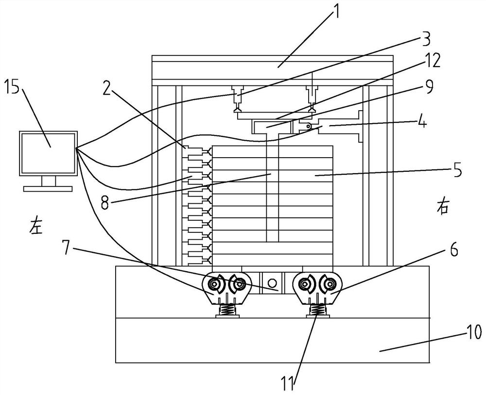
[0034] Specific implementation mode one: as figure 1 As shown, this embodiment discloses a simulation device for the composite stress mechanism of pile foundations in liquefaction sites, which is characterized in that it includes a reaction force frame 1 (made of hot-rolled I-shaped steel, which is a welded frame), a laminated shear model box 5. Model box loading device, horizontal circulation loading device, vertical loading device, saturated soil liquefaction excitation device and steel jacket 12;

[0035] The lower end of the reaction force frame 1 is fixed (by bolts) on the steel base plate 10 (the steel base plate 10 is fixed on the foundation), the vertical loading device is arranged in the reaction force frame 1, and the upper end of the vertical loading device Slidingly connected with the upper beam of the reaction frame 1, the lower end of the vertical loading device is connected with the upper end surface of the steel jacket 12, the pile cap 9 is fixed in the steel j...

specific Embodiment approach 2

[0038] Specific implementation mode two: as Figure 5 As shown, this embodiment is a further description of Embodiment 1. The vertical loading device includes at least two vertical loading hydraulic jacks 3 or at least two servo dynamic control systems (for the prior art); The lower end face of the upper beam of the reaction frame 1 is provided with a horizontal slideway along the left and right direction, and all the fixed ends of the vertically loaded hydraulic jacks 3 or the servo dynamic control system are slidingly connected with the horizontal slideway (each vertically loaded hydraulic jack 3 The fixed end of the jack 3 or the servo dynamic control system is provided with a slide block one, and the slide block one is slidably connected with the horizontal slideway), and the loading ends of all vertically loaded hydraulic jacks 3 or the servo dynamic control system are connected (by bolts) to the steel The upper end surface of the system outer cover 12 is fixedly connecte...

specific Embodiment approach 3

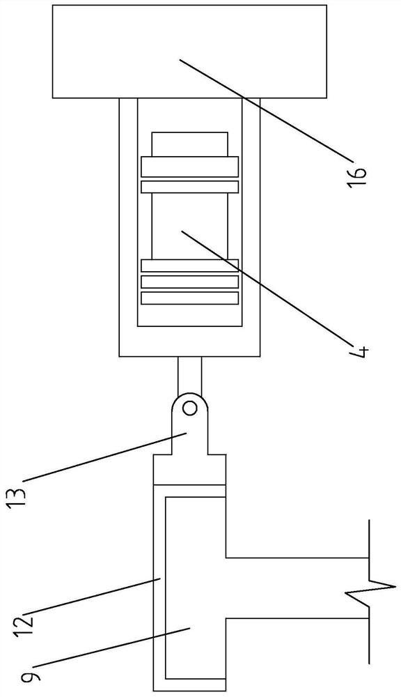
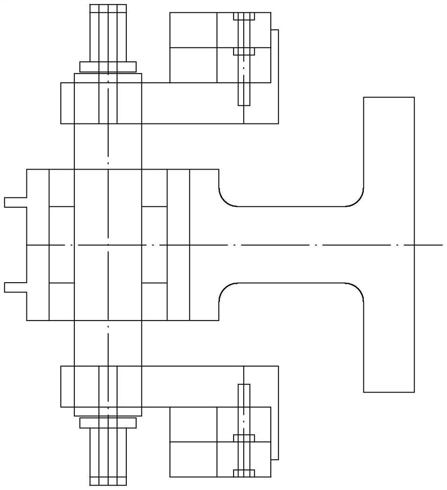
[0041] Specific implementation mode three: as figure 2 and Image 6 As shown, this embodiment is a further description of the second specific embodiment. The horizontal cyclic loading device includes a horizontal electromagnetic exciter 4 (an existing purchased part), a connecting seat 16 and an adapter 13 (an existing Outsourced parts); the two ends of the horizontal electromagnetic exciter 4 are respectively connected with the connecting seat 16 and the adapter 13, the adapter 13 is connected with the steel jacket 12, the steel jacket 12 is connected with the pile cap 9, and the Connecting seat 16 is arranged on the vertical slideway-sliding connection on the corresponding column of reaction force frame 1 (connecting seat 16 is provided with the slide block one that slides with the vertical slideway on the reaction force frame 1).

[0042] The purpose of applying a simple harmonic load to the pile cap 9 is achieved by passing a variable-amplitude alternating current to the...


PUM


Abstract

The invention discloses a liquefaction site pile foundation composite stress mechanism simulation device and a test method thereof and belongs to the technical field of rock-soil earthquake engineering. An upper end of a vertical loading device is in sliding connection with an upper cross beam of the reaction frame, a lower end of the vertical loading device is connected with an upper end face of the steel outer sleeve, a pile cap is fixed in the steel outer sleeve, a pile body is embedded into the laminated shear model box, and the bottom of the laminated shear model box is fixed to the saturated soil liquefaction excitation device; the horizontal cyclic loading device is in sliding connection with a vertical beam corresponding to the reaction frame, the horizontal cyclic loading device is connected with a pile cap through a steel jacket, and the model box loading device is in sliding connection with a vertical beam corresponding to the reaction frame; when the model box loading device works, the model box loading device is detachably connected with a frame body corresponding to the laminated shear model box, and the vertical loading device, the horizontal cyclic loading device, the model box loading device and the saturated soil liquefaction excitation device are connected with a computer through data lines. The device is used for simulating the composite stress mechanism of the pile foundation of the liquefaction site.

Description

technical field [0001] The invention belongs to the technical field of geotechnical earthquake engineering, and in particular relates to a simulation device and a test method for a pile foundation composite stress mechanism in a liquefaction site. Background technique [0002] In some major projects, pile foundations will appear in the selection of foundation engineering schemes. Pile foundations have significant advantages in reducing foundation settlement, seismic performance and comprehensive cost. However, in some engineering practices, various problems will also appear in pile foundations. For example, in the fields of slope engineering, port coast and offshore engineering, and high-speed railway engineering, according to past statistics, after liquefaction of inclined sites, The liquefied soil will push the pile foundation, and the pile will undergo bending failure and buckling failure under the combined force of the vertical load and the liquefied soil on the pile. T...

Claims


Application Information

Patent Timeline
Patent Type & Authority Applications(China)
IPC IPC(8): G01N3/12G01N3/24G01N3/38G01N3/02G01V1/02G01V1/30E02D33/00
CPCG01N3/24G01N3/12G01N3/38G01N3/02G01V1/02G01V1/307E02D33/00
Inventor 唐亮满孝峰贾喜军丛晟亦凌贤长李雪伟程志和邢文强
Owner HARBIN INST OF TECH
Why Eureka
Try Eureka