Parameterized bus bridge model design and modification method

A model design and busbar bridge technology, applied in the field of busbar bridges, can solve the problems of heavy design workload, low design efficiency, and heavy workload, and achieve the effects of reducing labor intensity, improving design efficiency, and ensuring design quality

Active Publication Date: 2021-06-29
HEBEI ELECTRIC POWER EQUIP
View PDF3 Cites 3 Cited by
  • Summary
  • Abstract
  • Description
  • Claims
  • Application Information

AI Technical Summary

Problems solved by technology

[0005]At present, the design of the busbar bridge still adopts the traditional design method, that is, each component of the busbar bridge needs to be modeled separately, and then obtained by assembling to meet the project requirements When encountering a similar but different-sized 3D model, it is necessary to modify the size information of all associated components. The reusability of the original model is low, the design workload is large, and the design efficiency is low. The contract performance of the project caused a lot of pressure
[0006]The existing design method is the most basic design and modification method for 3D models. Due to the poor correlation between parts and components, it requires a lot of work to modify, and It is relatively cumbersome and inefficient. Therefore, we propose a parametric bus bridge model design and modification method to solve the above problems

Method used


Image

  • Parameterized bus bridge model design and modification method
  • Parameterized bus bridge model design and modification method
  • Parameterized bus bridge model design and modification method

Examples


Embodiment Construction

[0030] The technical solutions in the embodiments of the present invention will be clearly and completely described below. Obviously, the described embodiments are only some of the embodiments of the present invention, but not all of them.

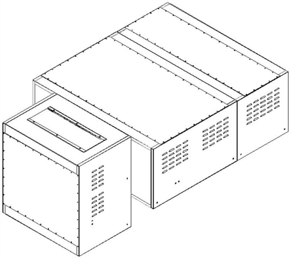
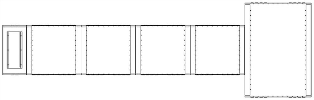
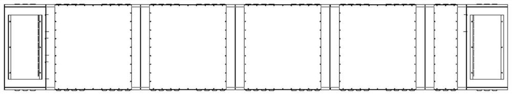
[0031] In the present invention, refer to Figure 1-7 , the application of SolidWorks overall parametric layout in busbar bridge design, and the shortcut form of SolidWorks in parametric design.

[0032] 1. Carry out the overall layout of the busbar bridge, according to the direction of the copper bars in the busbar bridge, make an overall layout of the structural position of the busbar bridge shell through the 3D sketch of SolidWorks, and add correlation equations to its main parameters, and control the main dimensions through the parameters.

[0033] 2. After completing the 3D sketch layout of the busbar bridge structure, set the datum plane with the help of the point lines of the 3D layout, and determine the specific position in space f...


PUM


Abstract

The invention discloses a parameterized bus bridge model design and modification method. The method comprises the following steps: S1, overall 3D sketch layout is carried out on a bus bridge; S2, after the 3D sketch layout of the bus bridge structure is completed, a datum plane is set by means of points and lines of the 3D layout, and the specific position of each part of the bus bridge in the space is determined; and S3, after the spatial positions of the bus bridge parts are determined, each part is drawn in sequence, the contour of each drawn part is restrained through the points and the lines of the 3D sketch layout in the step S1, and the contours of the parts and the 3D sketch layout generate an incidence relation. According to the method, parameterization of the bus bridge is convenient, rapid and efficient, continuous and repeated work is avoided, some unnecessary and repeated workloads are abandoned, the unnecessary labor intensity of technicians is reduced, the design efficiency is improved, the design quality of products is ensured, and the practicability is enhanced.

Description

technical field [0001] The invention relates to the technical field of busbar bridges, in particular to a parametric busbar bridge model design and modification method. Background technique [0002] The bus bridge, also known as the bridge connection, uses the jumper circuit breaker BCD to connect the two power supply lines with the main wiring of the two transformers. [0003] Parametric design means that the external shape of a part or component has been determined, and a set of parameters are used to constrain the relevant dimensions of the sketch geometry, and the parameters are associated with the control dimensions of the design object. When different parameter sequence values ​​are given, new parameters can be driven. The target geometry of , the design result of which contains the model of parametric information. Parameterization provides means for the variability of product models and concurrent design, so that users can use the previous model to rebuild the model ...

Claims


Application Information

Patent Timeline
Patent Type & Authority Applications(China)
IPC IPC(8): G06F30/392G06F30/394G06F30/398
CPCG06F30/392G06F30/394G06F30/398
Inventor 王君海李世杰郭书英张海霞郝雪楠朱丹李亚婷秦兆杰赵立胜
Owner HEBEI ELECTRIC POWER EQUIP
Why Eureka
Try Eureka