Supercharge Your Innovation With Domain-Expert AI Agents!

Automatic screw locking device for badminton racket production

A technology for automatically locking screws and badminton rackets, which is applied to cleaning methods using gas flow, cleaning methods and utensils, and metal processing. It can solve the problems of low work efficiency, manual locking, high labor intensity, and high production costs. The effect of high screw precision, less manual participation and low labor intensity

Pending Publication Date: 2021-07-02
上海迎轩体育科技有限公司
View PDF0 Cites 0 Cited by
  • Summary
  • Abstract
  • Description
  • Claims
  • Application Information

AI Technical Summary

Problems solved by technology

[0002] A badminton racket is generally composed of a racket head, a racket shaft, a handle, and the joint between the racket frame and the racket shaft. The length of a racket does not exceed 68 cm, of which the length of the racket handle and racket shaft does not exceed 42 cm, and the length of the racket frame does not exceed 25 cm. centimeters, the width is 20 centimeters, with the development of science and technology, the development of rackets is becoming lighter and lighter, the racket frame is getting harder, the racket shaft is getting better and better, and the air resistance is getting smaller and smaller. With the advancement of science and technology and the development of production technology, more and more automation equipment has been put into the production line. Automation operations have replaced manual simple and repetitive assembly line operations, which can effectively improve the productivity and competitiveness of enterprises. Most of the racket locking screws are done manually. Manual locking has high labor intensity, low work efficiency, high production cost, and has certain defects.

Method used


Image

  • Automatic screw locking device for badminton racket production
  • Automatic screw locking device for badminton racket production
  • Automatic screw locking device for badminton racket production

Examples


Embodiment Construction

[0015] The following will clearly and completely describe the technical solutions in the embodiments of the present invention with reference to the accompanying drawings in the embodiments of the present invention. Obviously, the described embodiments are only some, not all, embodiments of the present invention.

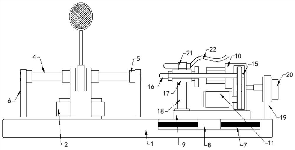
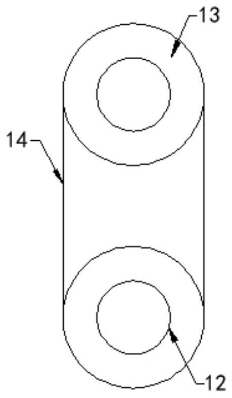
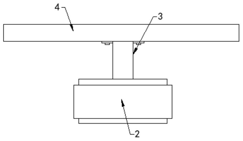
[0016] see Figure 1-3 , an embodiment provided by the present invention: an automatic locking screw device for badminton racket production, including a base 1, a first motor 2 is fixedly connected to the top of one end of the base 1, and a support rod is fixedly connected to the output end of the first motor 2 3. The top of the support rod 3 is fixedly connected with the turntable 4, and the outer wall of the turntable 4 is fixedly connected with a plurality of connection blocks 5, and the outer walls of the plurality of connection blocks 5 are fixedly connected with the installation block 6, and the installation block 6 is provided with There is a mounting groove, ...


PUM


Abstract

The invention discloses an automatic screw locking device for badminton racket production. The automatic screw locking device for badminton racket production comprises a base, a first motor is fixedly connected to the top of one end of the base, a supporting rod is fixedly connected to the output end of the first motor, a rotating disc is fixedly connected to the top end of the supporting rod, and a plurality of connecting blocks are fixedly connected to the outer side wall of the rotating disc. Mounting blocks are fixedly connected to the outer side walls of the multiple connecting blocks, mounting grooves are formed in the mounting blocks, a sliding groove is formed in the top of the other end of the base, a sliding rod is fixedly connected into the sliding groove, a sliding block slidably sleeves the sliding rod, and a mounting base is fixedly connected to the top end of the sliding block. The top of one end of the mounting base is fixedly connected with an equipment box, and the outer wall of one side of the equipment box is fixedly connected with a second motor. The automatic screw locking device for badminton racket production can synchronously lock screws of a plurality of products, the manual participation is less, the labor intensity is low, the screw locking precision is high, and the product quality is improved.

Description

technical field [0001] The invention relates to the field of products related to badminton racket processing, in particular to an automatic screw locking device for badminton racket production. Background technique [0002] A badminton racket is generally composed of a racket head, a racket shaft, a handle, and the joint between the racket frame and the racket shaft. The length of a racket does not exceed 68 cm, of which the length of the racket handle and racket shaft does not exceed 42 cm, and the length of the racket frame does not exceed 25 cm. centimeters, the width is 20 centimeters, with the development of science and technology, the development of rackets is becoming lighter and lighter, the racket frame is getting harder, the racket shaft is getting better and better, and the air resistance is getting smaller and smaller. With the advancement of science and technology and the development of production technology, more and more automation equipment has been put into ...

Claims


Application Information

Patent Timeline
Patent Type & Authority Applications(China)
IPC IPC(8): B23P19/06B27M3/22B27C3/00B08B5/02
CPCB23P19/06B27M3/22B27C3/00B08B5/02
Inventor 夏玉礼蔡雪王严峰刘雁田
Owner 上海迎轩体育科技有限公司
Features
  • R&D
  • Intellectual Property
  • Life Sciences
  • Materials
  • Tech Scout
  • Unparalleled Data Quality
  • Higher Quality Content
  • 60% Fewer Hallucinations
Learn More